I think this is my new reference desktop headamp
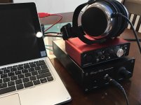
After extensive listening and actual use as a desktop amp paired with the Scarlett Solo 2G, I have to say that I am really happy with the sound. So much so that this is my new reference desktop headamp. In practice, it works superbly as well - no turn on/off thump (thanks to the slow start/stop feature of the cap bank and cap multiplier), no noises from connecting or disconnecting phone jack while powered up, absolutely no noise from any pot movement (cannot tell it is on if no music playing). The Solo 2G as DAC for my laptop seems to fit perfectly sitting on top as the two are same width and have a similar look. The sound is about as close to perfect as I have ever heard. The BF862 and 2SA1837 combo with a cap bank and cap multiplier seems to do the trick. Note that there is only a single power supply connected to both channels but it achieves a nice measured -88.5dB stereo crosstalk figure (thanks to cap bank I think).

This combo with Beyerdynamic DT880-250, Focusrite Solo 2G, laptop, and BF862-2SA1837 two transistor SE headamp is just about perfect.
After extensive listening and actual use as a desktop amp paired with the Scarlett Solo 2G, I have to say that I am really happy with the sound. So much so that this is my new reference desktop headamp. In practice, it works superbly as well - no turn on/off thump (thanks to the slow start/stop feature of the cap bank and cap multiplier), no noises from connecting or disconnecting phone jack while powered up, absolutely no noise from any pot movement (cannot tell it is on if no music playing). The Solo 2G as DAC for my laptop seems to fit perfectly sitting on top as the two are same width and have a similar look. The sound is about as close to perfect as I have ever heard. The BF862 and 2SA1837 combo with a cap bank and cap multiplier seems to do the trick. Note that there is only a single power supply connected to both channels but it achieves a nice measured -88.5dB stereo crosstalk figure (thanks to cap bank I think).
This combo with Beyerdynamic DT880-250, Focusrite Solo 2G, laptop, and BF862-2SA1837 two transistor SE headamp is just about perfect.
Attachments
Last edited:
")
New thread to listen to all my headamps.
http://www.diyaudio.com/forums/soli...al-audition-several-headamps.html#post4977888
http://www.diyaudio.com/forums/soli...al-audition-several-headamps.html#post4977888
I adjusted the R6 pot for exact balance and match of harmonic distortion profile between left and right channels. THD is now at 0.0072%. H2 is at -86dB and H3 is at -96dB.
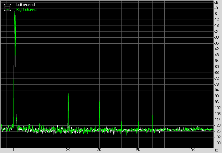
There must be something to burning in because I now measure THD at 0.0056% after playing music for 24hrs on the amp. Dynamic range is measured at 92dB and IMD+N measured at 0.0091%. These numbers are almost approaching some opamp based headamps that I have, but doing it with the immediacy and impact of 2 transistors in pure SE Class A.
Find out how you can get free Pocket Class A Headamp (built and tested):
http://www.diyaudio.com/forums/head...-audition-several-headamps-5.html#post4981007
http://www.diyaudio.com/forums/head...-audition-several-headamps-5.html#post4981007
Last edited:
Sam,
I will answer this, as X is sleeping!
You normally design for dual power supplies so that you can remove caps, making the amp direct coupled.
In this design, the input potential is about 3.5V above ground, and the output at around 12V above ground. The usual technique would be to direct couple the output to improve DF on the 'speaker'. In this case, the requirement is somewhat less because cans generally deliver very good bass, but at the same time are very sensitive to DC voltage. So we'd have to use a cap on the input, rather than the output.
Since a dual rail, positive and rail, bipolar supply is more complex (and we'd have to put the output at midway potential which costs output range), we would have to use a cap on the input. The decision to use a unipolar supply was therefore suitable. It would guarantee the HP would never see a DC voltage, but more importantly, there were two non-zero potentials on both caps which would polarise them, and thereby improve their sound quality because the dielelectric was 'stressed' into the linear region.
Ergo, we used a single unipolar and then took some steps to remove the thump at turn on.
HD
Last edited:
Sam,
I will answer this, as X is sleeping!
thank you
Sam,
I will answer this, as X is sleeping!
Ergo, we used a single unipolar and then took some steps to remove the thump at turn on.
HD
Could you go into a little detail about the steps taken to eliminate the power up thump?
For a desktop amp, use a capacitance multiplier like the one I used here:
http://www.diyaudio.com/forums/solid-state/297921-jumas-easy-peasy-capacitance-multiplier.html
It basically brings the voltage up slowly over 20seconds avoiding turn on thump. In addition it brings power supply ripple down to the 100uV level. It also slowly lowers the voltage when you cut the power avoiding turn off thump.
For portable amps you need a relay and a delay circuit. Many amps do this.
On my desktop reference amp you can see my cap Mx near the back of the amp followed by a cap bank. The photo shown has an earlier LU1014D based power JFET amp stage. I have since replaced it with a 2SA1837 CFP power amp stage. Still running 20v rails though. The cap Mx using IRFP240 suffers a 4v drop which is perfect for amps that have 20v limit.
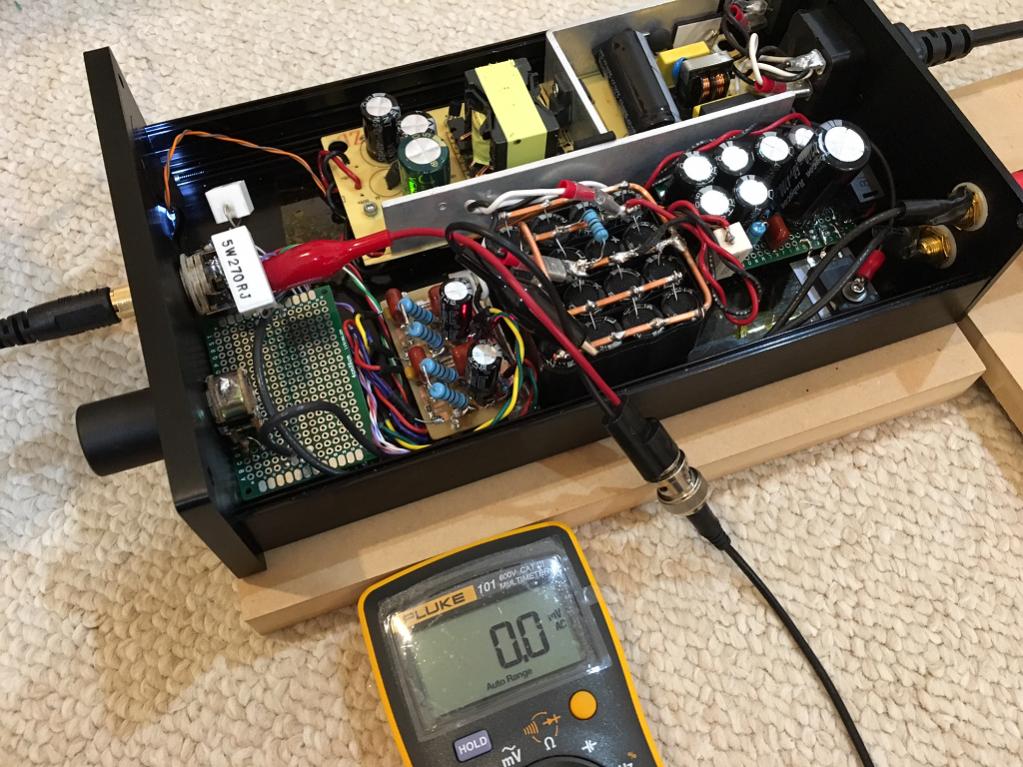
I am using a 24v SMPS for LED light string taking up the entire left side.
You could also avoid thump with a large CRC cap bank. Just calculate the RC constant to be about 3sec.
http://www.diyaudio.com/forums/solid-state/297921-jumas-easy-peasy-capacitance-multiplier.html
It basically brings the voltage up slowly over 20seconds avoiding turn on thump. In addition it brings power supply ripple down to the 100uV level. It also slowly lowers the voltage when you cut the power avoiding turn off thump.
For portable amps you need a relay and a delay circuit. Many amps do this.
On my desktop reference amp you can see my cap Mx near the back of the amp followed by a cap bank. The photo shown has an earlier LU1014D based power JFET amp stage. I have since replaced it with a 2SA1837 CFP power amp stage. Still running 20v rails though. The cap Mx using IRFP240 suffers a 4v drop which is perfect for amps that have 20v limit.
I am using a 24v SMPS for LED light string taking up the entire left side.
You could also avoid thump with a large CRC cap bank. Just calculate the RC constant to be about 3sec.
Last edited:
No, sorry I made hand drawn PCB's using a Sharpie marker as etch resist. It's such a simple amp you should try hand drawing your layouts sometimes - nice custom organic look.
Try pinging one of the other members who specialize in layouts. I don't know how to layout in CAD.
BF862 is standard SOT23 package. LU1014D is strange. Similar pins to package size of BD139 (TO225). Try using that. Of course pinouts are different. The heatsink tab on LU1014 is very small and requires main body to be clamped to heatsink with a pressure bar and two screws. Alternatively, one can reflow solder the LU1014 onto a copper block (an old TO220 tab) and then use the the TO220 mounting screw hole.
Last edited:
I need Eagle libraries for bf862 and LU1014d
Thanx
I use the SST201 footprint for the BF862, which comes with the default Eagle libraries. Happily, the BF862 drain and source pins are interchangeable.
The LU1014d package is TO251, which you can find here: DIYmodules.org - Free EAGLE Libraries, Tools for Electronics Designers
- Home
- Amplifiers
- Headphone Systems
- BF862 based SE Class A Headamp without the HEAT