Here's a picture
Salas,
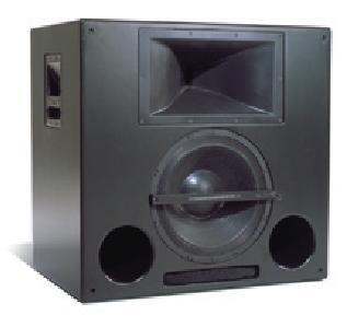
Here's a picture of the "Gecko" from last year:
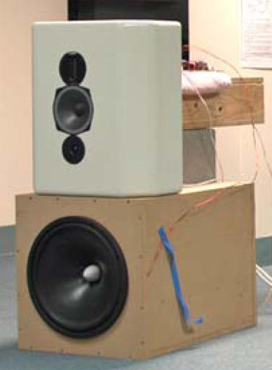
This picture was taken when I had the speakers on a demonstration at a Pacific Northwest Audio Society (PNAS) meeting. They put a short summary of the presenation of the "Gecko's" in their newsletter. There is a passive crossover in this picture, which was built specifically to enter the "Puget Sound" speaker contest sponsered by the PNAS. It is normally a fully active system.
This was during the tweeter audition period of the project, and I had two tweeters in the baffle for comparison - an Hiquophon OW1 and an Aurum Cantus G2si. After extended auditions, I chose the OW1, and have since removed the G2si and blanked the hole in the baffle.
Edward
salas said:P.S. Can you post picture here?
Salas,
Here's a picture of the "Gecko" from last year:
This picture was taken when I had the speakers on a demonstration at a Pacific Northwest Audio Society (PNAS) meeting. They put a short summary of the presenation of the "Gecko's" in their newsletter. There is a passive crossover in this picture, which was built specifically to enter the "Puget Sound" speaker contest sponsered by the PNAS. It is normally a fully active system.
This was during the tweeter audition period of the project, and I had two tweeters in the baffle for comparison - an Hiquophon OW1 and an Aurum Cantus G2si. After extended auditions, I chose the OW1, and have since removed the G2si and blanked the hole in the baffle.
Edward
More details
Lynn,
The crossover points are ~350 and ~3500, 4th order with time alignment (delay). Yes, the OW1 crosses in quite high because of the extended bandwidth of the PHL 1120.
The pre-ringing is a data processing artifact. I just made a whole bunch of measurements of the system over the Labor day holiday weekend, but did not save the impulse responses, just the FR's. The pre-ringing is a by-product of running an inverse FFT on the FR dataset - which is bandwidth limited.
Edward
Lynn Olson said:
Nice time response - again, I doubt very much any horn or waveguide could match that, at least from the data I've seen published. This takes us to electrostatic territory with much better dynamics thrown in. Curious about the crossover points you've chosen - I imagine the 3/4" HF driver is crossed fairly high, to take advantage of the PHL's extension.
Curious about the pre-ringing over the first 300 microseconds - it's not easy for a tweeter to do that, it looks more like a sound card artifact due the built-in anti-alias lowpass filter - set to 20 or 40 kHz, maybe? Although my MLSSA card is ancient, dating back to 1991, I run it at 120 kHz to avoid lowpass filter artifacts and see what the tweeter is really doing. If the pre-ringing is what I think it is, your speaker is actually better than what's shown above.
I find the rapid decay in the time response corresponds to depth portrayal, or spatial fidelity - not imaging or reverb per se, but an accurate impression of the actual size of the performing venue. Weirdly enough, you can actually sense this before any music starts to play, or likewise with applause, which is extremely revealing of transient distortion and midrange/HF coloration.
Lynn,
The crossover points are ~350 and ~3500, 4th order with time alignment (delay). Yes, the OW1 crosses in quite high because of the extended bandwidth of the PHL 1120.
The pre-ringing is a data processing artifact. I just made a whole bunch of measurements of the system over the Labor day holiday weekend, but did not save the impulse responses, just the FR's. The pre-ringing is a by-product of running an inverse FFT on the FR dataset - which is bandwidth limited.
Edward
salas said:... and double 6X9s shielded.
Yes... as many others I have been following this thread with interest since there are excelent contributions...
I know you might have already given details of your set up but by this time they are burried some place on this thread.
Could you elaborate on the HF driver you are using? also XO points? pasive XO? order of XO?
Thanks
apassgear said:
Yes... as many others I have been following this thread with interest since there are excelent contributions...
I know you might have already given details of your set up but by this time they are burried some place on this thread.
Could you elaborate on the HF driver you are using? also XO points? pasive XO? order of XO?
Thanks
In a nutshell, I use a 26lt closed box with 2x Tangband 6X9s (W69-1042). A second box houses a PHL1220, and a time aligned Audax A20, but moded with a 4 Ohm diaphragm. A foam packed slit runs the back and aperiodically vents the PHL. The Tweeter is unobtainium. Sensitivity is 94dB overall.
Passive XO. Nothing on the woofers, 6dB low pass & 12dB high pass for the PHL, 18dB for the tweeter. You can see its response and crossing in the attached chart, room modes, warts, and all. The design axis is high, in-line with the cabinet's top.
Attachments
Hi there Dr. Geddes, are these the curves you're referring to? If I'm reading them correctly, it looks like it takes the Summa/ESP15 about 1.5~2 mSec (depending on interpretation) to visibly quiet down to zero. But maybe I'm not reading it right, and have got the scales wrong, or copied the wrong set of data from your papers.
Maybe we can get Tom Danley's impulse data as well - AFAIK, the Summa/ESP15 and the Unity systems have the best impulse response for waveguides (and horns) out there - I've never seen anything better.
Maybe we can get Tom Danley's impulse data as well - AFAIK, the Summa/ESP15 and the Unity systems have the best impulse response for waveguides (and horns) out there - I've never seen anything better.
Attachments
Been pawing through the ol' hard disk, and found this pix for Tom Danley's SH-50 Synergy horn. Reduced it by 2/3 so it would fit into the diyAudio size limits, and then re-sharpened in Photoshop - sorry about the crunchy appearance.
Hmm - decay time is kind of hard to judge here, with some visible clutter all the way out to 10 mSec. Most of it seems gone by 3~4 mSec, though, if I'm reading it right.
If either Dr. Geddes or Tom have more recent impulse data, many of the readers (including me) would love to see it. Impulse data for horns and waveguides seems very hard to come by - you sure don't see it on the prosound sites, that's for sure - all those guys do are those 1/3 octave smoothed "happy graphs".
One of the things I like most about impulse (and CSD) data is there's no good way to "smooth" it, so you're always looking at the as-is microphone response (although this can be sometime degraded by digital lowpass filtering - the giveaway is HF pre-ringing).
Attachments
As for off-axis impulse response, unfortunately I don't have many of the old MLSSA Ariel measurements stashed on this computer, but back when I was last measuring it in 1994, I don't recall any dramatic changes with the off-axis response. I would have been surprised to see much change at all, considering I took some steps to reduce cabinet-edge diffraction, the 4th-order acoustic Linkwitz-Riley crossover wasn't very sensitive to off-axis shifts, and all three drivers had very wide measured dispersion. Considering their tiny size and close mounting, not surprising.
If there was a net 90-degree phase angle between the drivers, as with an acoustic 1st or 3rd-order crossover, they tended to be more sensitive to off-axis changes. The first version of the Ariel started out with a really simple 1st-order crossover, and I noticed it was quite a bit more sensitive to off-axis response shifts. Coloration levels were higher as well, which prompted the change to a little more serious crossover.
If there was a net 90-degree phase angle between the drivers, as with an acoustic 1st or 3rd-order crossover, they tended to be more sensitive to off-axis changes. The first version of the Ariel started out with a really simple 1st-order crossover, and I noticed it was quite a bit more sensitive to off-axis response shifts. Coloration levels were higher as well, which prompted the change to a little more serious crossover.
Attachments
Two of the reasons I get such clean time data is the choice of a 120 kHz sample rate with a programmable 25 kHz Bessel lowpass filter for the ADC, and a rather unusual mike stand for the ACO Pacific 1/2" condenser microphone.
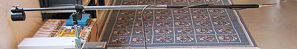
My friend Mike Spurlock, who owned the stacked Quad ESL57's was a welder for the City of Portland, and he made this custom mike stand for me. As you can see, it's a counterweighted 1/2" steel rod about 1.5 meters long, and there's a special machined-plastic adaptor between the 1/2" diameter microphone and the same-diameter rod.
Mike Spurlock simply took a 6-inch length of 1/2" (ID) plastic pipe, cut a narrow slit in it lengthwise, and machined and polished the end facing the microphone, so the adapter has an curved, jet-engine nacelle appearance as seen from the microphone. One end is a snug fit to the rod, the other to the microphone, and the slit is just large enough so the mike cable can pass through and then be wound around the length of the steel rod. Net result, very little surface for any diffraction at all, except for the (commercial) vertical mike stand, which is a full 1.5 meter away from the microphone capsule.
The transparent plastic sleeving on the rear end of the steel rod is there so the mike-stand has something to grip on - the black paint on the steel rod turned out to be kind of slippery, letting the whole thing tilt down if it wasn't perfectly counterbalanced.
The curvature you see in this pix isn't there in reality - cheap digital camera gets the blame there. The steel rod, as you might expect, is quite straight and doesn't visibly sag at all.
Since I'm kind of a perfectionist about measuring tweeters accurately, I didn't like what I saw with commercial mike stands, and was really pleased what Mike Spurlock came up with. Since he was the original "customer" for the Ariels - which were voiced to sound like Mike's stacked Quads - it's appropriate that Mike designed this stand that made the data-gathering possible.
If mike-stands like this were more widely used, I think people would more easily see time-domain clutter from the loudspeaker on their MLS and FFT systems, and could then take effective steps to reduce it. When the speaker performance is cluttered with measurement artifacts, it really is much harder to see some of the subtler effects of cabinet-edge diffraction and internal reflections inside cabinets.
Attachments
salas said:And a photo. We must apologize to Lynn for abusing his thread though. But yes, you are right, I have posted bits here and there in the past so it must be difficult for you to collect.
Just to close this OT, Sorry Lynn.
You got some serious stuff there Salas, very nice gear including speakers, Thanks for your response.

Here is a horn system published impulse
Lynn,
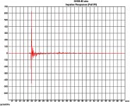
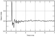
Here is (my version of) a published impulse response from the Meyer Sound X10 studio monitor: (I trimmed 4 milliseconds of flat-line off the front and two milliseconds off the back of the chart)
(The subtitle is theirs)
This is a picture of the product:
Clearly, there is a lot of 'rumbling' in this impulse. This system has a solid millisecond of 'hash'. Perhaps this is attributable to Dr. Geddes' evil HOM's.
Anyway, this offers another datapoint to the discussion. The full datasheet can be found here on the Meyer Sound website.
Edward
Lynn Olson said:Impulse data for horns and waveguides seems very hard to come by - you sure don't see it on the prosound sites, that's for sure - all those guys do are those 1/3 octave smoothed "happy graphs".
Lynn,
Here is (my version of) a published impulse response from the Meyer Sound X10 studio monitor: (I trimmed 4 milliseconds of flat-line off the front and two milliseconds off the back of the chart)
(The subtitle is theirs)
This is a picture of the product:
Clearly, there is a lot of 'rumbling' in this impulse. This system has a solid millisecond of 'hash'. Perhaps this is attributable to Dr. Geddes' evil HOM's.
Anyway, this offers another datapoint to the discussion. The full datasheet can be found here on the Meyer Sound website.
Edward
A question about those impulse graphs:
What is all the stuff before the impulse? I know some is ADC filter artifacts, I've seen them on my measurements, but is all of it filter junk? Or is it coming from other things?
Why is there so much going on before the impulse?
BTW, I like the Meyer chart, at lest it puts the zero time mark right at the impulse.
panomaniac said:A question about those impulse graphs:
What is all the stuff before the impulse? I know some is ADC filter artifacts, I've seen them on my measurements, but is all of it filter junk? Or is it coming from other things?
Why is there so much going on before the impulse?
BTW, I like the Meyer chart, at lest it puts the zero time mark right at the impulse.
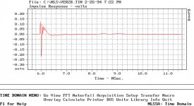
In the case of my impulse, all the 'junk' before the impulse - and the 'wiggling' after the impulse (2.5 to 4 ms) - is the result of bandwidth limiting. My impulse was generated by using an inverse FFT on the frequency response data - which had been truncated after the orginal FFT. On the Meyer sound impulse, I would guess that the initlal signal before the spike is the woofer signal leading the horn a bit - slight time misalignment.
Edward
EdwardWest said:
On the Meyer sound impulse, I would guess that the initlal signal before the spike is the woofer signal leading the horn a bit - slight time misalignment.
Edward
I think that must be the greatest woofer of alltime, or they left it out.
Lynn Olson said:Hi there Dr. Geddes, are these the curves you're referring to? If I'm reading them correctly, it looks like it takes the Summa/ESP15 about 1.5~2 mSec (depending on interpretation) to visibly quiet down to zero. But maybe I'm not reading it right, and have got the scales wrong, or copied the wrong set of data from your papers.
Maybe we can get Tom Danley's impulse data as well - AFAIK, the Summa/ESP15 and the Unity systems have the best impulse response for waveguides (and horns) out there - I've never seen anything better.
From what I can see the Unity doesn't look all that good at all.
Impulse responses are dangerous things to look at because some things that aren't problems look bad and things that are problems aren't readily apparent. For example, virtually all of the ringing hash in the Summa impulse is the CD ringing at 16 kHz. which is very undamped as the FFT shows. But IMO this is not a problem since virtually no one can hear very well at 16 kHz. (my cat objects, but I don't). So exclude this ringing and the impulse dies in about .5 ms.
Impulse responses are linear in magnitude and we hear more logarithmically. Hence much detail that we can hear is lost into the picture. Impulses tell SOME of the story, but not it all. I look for delayed effects - just like I see in the Unity impulse.
By the way someone posted an impulse said to be of a Meyer system. This impulse is impossible since it is a single spike - not two. No acoustic source can have only a single spike. It must be a doublet.
gedlee said:By the way someone posted an impulse said to be of a Meyer system. This impulse is impossible since it is a single spike - not two. No acoustic source can have only a single spike. It must be a doublet.
Earl,
Could you clarify "This impulse is impossible since it is a single spike - not two."
The loop-back of a measurement system is a single spike. Transient-perfect multi-way systems have a single spike. In this context, I do not understand your statement. Could you expand on your observation?
Thanks,
Edward
salas said:No negative going spike?
Salas,
In my experience a negative going spike is not a de facto requirement in acoustic sources. Transient-perfect speaker systems that I am aware of have only the single spike. For example, this is a measured impulse of a design which John Kreskovski developed, based upon the "B&O Filler Driver Concept".
An externally hosted image should be here but it was not working when we last tested it.
Based upon my understanding, I am confused by Dr. Geddes statement, which is why I ask for an expansion of his observation.
Edward
- Home
- Loudspeakers
- Multi-Way
- Beyond the Ariel