..The speakers will have higher 2nd and 3rd harmonics, but virtually nothing above that - and here is the point - no matter how much excursion the speaker sees.
..emphasis added.
Plus, I've seen several different drivers from B&C and some have very low higher harmonics, and others - not so much. Ex.
https://sites.google.com/site/drivervault/driver-measurements/15/b-c-15nw76/non-linear-distortion
Really though, with any good motor - the motor's relevance with respect to harmonic distortion is comparatively LOW within a linear excursion range.
By far harmonic distortion is the result of non-linearity with the driver's spider. (..klippel measurements bear this out.)
Last edited:
Power-supply design is one of the big differences between the solid-state and vacuum-tube world. At a wild guess, maybe 10 to 20% of tube amps have correctly designed (non-ringing, non-overshoot) choke-fed supplies. The same kind of supply is super-rare in the transistor world, probably well under 0.1% of amps sold to audiophiles (never mind mass-market).
Unless you are sure the power supply is low emission, it's safe to assume to it's a big noisemaker, with very high current switching pulses at a 100 or 120 Hz rate. These pulses not only have near-squarewave risetimes, but glitches (holes) due to charge-storage effects in the silicon diodes. Soft-recovery or HEXFRED diodes get rid of the glitches, but do not get rid of of the switching current pulses. It takes an inductor that's rated for the (measured) peak currents of the PS circuit to do that, and inductors cost money and add size and weight to the chassis (they're typically as big as the power transformer itself). If it's a stereo amplifier, it's not good practice to share the inductor between channels (PS crosstalk), so you'll need two of them.
I've heard transistor amps that have well-designed full regulation for the entire amplifier, along with low switch-noise emission, and surprise, they sound like very good tube amps. Which tells us something about the other 99.9% of the amps out there, and why there's a big market for power cords and power conditioners.
Minor aside: the Karna sounds worse with audiophile power cords, and really bad with audiophile power conditioners. It thrives on heavy-duty 12-gauge cords for industrial applications, and being plugged directly into the power outlet.
Kinky geek-note: I've seriously considered getting a motor-generator set to place in the garage, so I have nice clean 60 Hz 120V power with pretty sine waves for the audio system. The sine waves that come off the power line have some nasty flat-topping and other glitches, thanks to other houses in the neighborhood with all those switchmode power supplies for TVs and computers.
We cannot all live in Sweden.
") My tube amp has much less hum in Sweden than in Norway. Try a top of the line Isotek or similar. It can recreate a the Swedish power grid in your livingroom. Or so I was told by the seller in Norway.
My tube amp has much less hum in Sweden than in Norway. Try a top of the line Isotek or similar. It can recreate a the Swedish power grid in your livingroom. Or so I was told by the seller in Norway.http://m.isoteksystems.com/a/1/p/16
Last edited:
Of interest, to do an all-out assault on the 20 to 100Hz range, with the least 2rd and 3rd harmonics generation up to realistic levels, which specific drivers would people recommend?
Me too. As a result of recent Skype/telephone conversations with Alexander of RAAL and Gary Dahl, it has occurred to me that band-splitting is a better way of reducing IM distortion than simply doubling-up drivers. In other words, rather than two drivers covering F3 to 700 Hz, better to have a F3 to 100~200 Hz range, and a 100~200 Hz to 700 Hz range, with separate amplification and equalization for the deep LF range. Maybe head-smackingly obvious, but sometimes several people have to tell me the same thing before I get it.
The requirements for the deep LF and LF/MF drivers are not the same. The LF/MF driver, in this case the GPA/Altec 515 Alnico, has a measured efficiency of 98.6 dB/meter/watt, a Qts between 0.19 and 0.2, and modest Xmax. It will be powered with a 20-watt triode amplifier, and there's no point in using it below 100 Hz. A small LF/MF closed box, or closed-box combined with highpass filter (resulting in a synthesized 3rd or 4th-order highpass), will restrict excursion to the linear region.
The deep LF drivers, as per Dr. Geddes excellent suggestion, can be a pair of B&C 15" drivers, one on the left side of the LF closed-box, and the other on the right side of the same LF closed-box, with rods going between the two for reaction cancellation (hat tip to Alexander).
They are powered by big bad transistor amplifiers, with analog parametric or digital equalization that corrects for LF shape (using the trendy phrase, a Linkwitz transform) and notching out the dominant room peaks. Since my room, and Gary Dahl's, are not symmetric, the LF equalization for the Left and Right channels needs to be independent.
The 100~200 Hz crossover is not especially critical; it needs to keep excursion down for the LF/MF driver, and the overlap region (if any) will depend very much on prevailing room modes.
If the DIY'er has enough space, a LF/MF bass horn is a great idea, since the crossover frequency ends up being the same.
Last edited:
By far harmonic distortion is the result of non-linearity with the driver's spider. (..klippel measurements bear this out.)
The compliance nonlinearity can be high, but the compliance is only a factor below resonance not above where the system is mass controlled. And in a closed box the compliance is swamped out by the box's air compliance which is very linear (by comparison.) Hence the compliance nonlinearity can be made to be insignificant. On the other hand the BL nonlinearities act throughout the whole frequency range and cannot be linearized by any external factor.
Actually the most important nonlinearity for a wide range driver is the inductance because it can act on the current as well as the excursion and the current can still be high even if the excursion is low. Flux demodulating rings will minimize this nonlinearity to insignificant as well.
Last edited:
Me too. As a result of recent Skype/telephone conversations with Alexander of RAAL and Gary Dahl, it has occurred to me that band-splitting is a better way of reducing IM distortion than simply doubling-up drivers. In other words, rather than two drivers covering F3 to 700 Hz, better to have a F3 to 100~200 Hz range, and a 100~200 Hz to 700 Hz range, with separate amplification and equalization for the deep LF range. Maybe head-smackingly obvious, but sometimes several people have to tell me the same thing before I get it.
The requirements for the deep LF and LF/MF drivers are not the same. The LF/MF driver, in this case the GPA/Altec 515 Alnico, has a measured efficiency of 98.6 dB/meter/watt, a Qts between 0.19 and 0.2, and modest Xmax. It will be powered with a 20-watt triode amplifier, and there's no point in using it below 100 Hz. A small LF/MF closed box, or closed-box combined with highpass filter (resulting in a synthesized 3rd or 4th-order highpass), will restrict excursion to the linear region.
The deep LF drivers, as per Dr. Geddes excellent suggestion, can be a pair of B&C 15" drivers, one on the left side of the LF closed-box, and the other on the right side of the same LF closed-box, with rods going between the two for reaction cancellation (hat tip to Alexander).
They are powered by big bad transistor amplifiers, with analog parametric or digital equalization that corrects for LF shape (using the trendy phrase, a Linkwitz transform) and notching out the dominant room peaks. Since my room, and Gary Dahl's, are not symmetric, the LF equalization for the Left and Right channels needs to be independent.
The 100~200 Hz crossover is not especially critical; it needs to keep excursion down for the LF/MF driver, and the overlap region (if any) will depend very much on prevailing room modes.
If the DIY'er has enough space, a LF/MF bass horn is a great idea, since the crossover frequency ends up being the same.
I agree with this concept, based purely on looking at what a drivers cone has to do to reproduce 20 to 80Hz. My solution is a 16 Hz LeCléach bass horn with a B&C 18" driver. I need to emphasise that I have no expertise at all in this, other than my personal system which is yet to work in its entirety.
The compliance nonlinearity can be high, but the compliance is only a factor below resonance not above where the system is mass controlled.
And in a closed box the compliance is swamped out by the box's air compliance which is very linear (by comparison.) Hence the compliance nonlinearity can be made to be insignificant. On the other hand the BL nonlinearities act throughout the whole frequency range and cannot be linearized by any external factor.
Actually the most important nonlinearity for a wide range driver is the inductance because it can act on the current as well as the excursion and the current can still be high even if the excursion is low. Flux demodulating rings will minimize this nonlinearity to insignificant as well.
That sounds right, so I must be reading the Klippel measurements wrong..
I think it's the break-down of distortion products that I'm having problems with.
Ex. Scanspeak 18wu/4741t00
Attachments
Last edited:
Wow, totally agree with this. I do wonder why B&C does not publish their Klippel data, but from one I could find on the web, it looks great. Wish they had metal cones or carbon composit cones.I did not write my review as an advertisement for B&C, but to state why I think that the prevailing philosophy of motor BL design is not really correct. B&C just happens to do it right that's all. I still hear people talk about how the BL curve should be flat and that is just not the best way to do it.
I like the rounded BL curve too. They behave quite nicely up to mechanical bottoming or suspension limits; easier to design suspensions for optimum match; also easier to compensate for in match amplifier design.Art - since I never said that they did your comment is moot. I said that one should minimize the higher orders by letting the lower ones rise. I alluded to B&C appearing to do this.
You really need to read what I say better.
I have no idea if the speaker that you posted in done right or not. Some B&C drivers posted in Voice Coil did show a very smooth rounded BL curve, quite symmetric - clearly done intentionally. I have no idea how prevalent this is in their products, just that I know that they have done it for some. Most people believe what Kindhornman states - I don't, which is why I posted what I did.
Earl,
Again we are in agreement that the spider in most instances is a non-linear factor in the speaker, this can be looked at as a separate design element that can be linearized but it is not common.
I also agree that a Faraday ring is very important to smoothing the impedance rise of the drive but at the same time many designs use the rings in a very inefficient manner. I posted the impedance curve and phase response of the speaker I am working on earlier and was surprised that I got not one comment.
Lynn,
I was going to ask you about using a combination of an 18" speaker for the extreme lows and a 15" above that for the higher frequencies. Now don't ask me to recommend an 18" speaker as I really don't know them intimately as to the fs values. The only reason I suggest the 18" is the cone area can move so much more air than a 15" with so little excursion. I do have a 24" speaker that I acquired in the past that I have thought about using as a subwoofer but there are no specifications and I have not run the Thiel Small values. From what I can see it looks like a copy of a JBL 18" driver with a larger frame and cone and the motor looks like a copy of a standard ceramic motor assembly.
soongsc,
I think that a metal cone 15" driver would have a very different sonic quality than the B&C drivers that you seem to like. I personally don't like metal cones, they usually have some severe breakup modes with high Q resonances. I work with carbon fiber cones and make my own and I will say that it is not necessarily easy to make one that sound good and measures well. One of the problems that I have seen is like a metal cone driver is that it is very easy to make the cone to stiff. It is a balance that has to be made to control the material properties of the fiber content and the matrix resins.
I think that a metal cone 15" driver would have a very different sonic quality than the B&C drivers that you seem to like. I personally don't like metal cones, they usually have some severe breakup modes with high Q resonances. I work with carbon fiber cones and make my own and I will say that it is not necessarily easy to make one that sound good and measures well. One of the problems that I have seen is like a metal cone driver is that it is very easy to make the cone to stiff. It is a balance that has to be made to control the material properties of the fiber content and the matrix resins.
I like rounded BL curves for many reason other than already mentioned. But it is the matching of suspension and BL curve that is important. This is a complicated issue because from linear point of view, you want linear net force across the excursion, not jus linear BL, but when you have linear net force, there are concerns running the motor into a non-stable state.
In a few seminars Mr. Klippel had a different idea about what the optimum BL curve should look like, and I agree with him as long as there is appropriate compensation electronically.
In a few seminars Mr. Klippel had a different idea about what the optimum BL curve should look like, and I agree with him as long as there is appropriate compensation electronically.
True, metal cones and other hard cones are difficult to design. Totally stiff is not the answer. Since currently one objective of mine is to get a cone to work well over the widest range without the higher modes contributing to bandwidth, this means having better control of the modes. This is about all I can reveal before the patent is approved which will take a few years. First application will be in a driver about 6.5 inches. The design was dreamed up because the current patent is too labor intensive, but it still could be applied in addition to the new patent.soongsc,
I think that a metal cone 15" driver would have a very different sonic quality than the B&C drivers that you seem to like. I personally don't like metal cones, they usually have some severe breakup modes with high Q resonances. I work with carbon fiber cones and make my own and I will say that it is not necessarily easy to make one that sound good and measures well. One of the problems that I have seen is like a metal cone driver is that it is very easy to make the cone to stiff. It is a balance that has to be made to control the material properties of the fiber content and the matrix resins.
The reason why pro audio can tolerate paper cones is that they are usually played at high level signals, absorption of energy of the paper is significantly smaller in percentage when you compare against home audio listening levels.
To make it clear, it is the type of BL curve that I like, not necessarily B&C.
Measure, measure, test, test, test before you do! My house has a 12 KW / 230V generator attached. It's a serious, gas fired rig sitting on a concrete slab. And the sine waves it puts out are ugly. Really ugly. Great for running the whole house during an ice storm, but not wonderful for powering audio gear.Kinky geek-note: I've seriously considered getting a motor-generator set to place in the garage, so I have nice clean 60 Hz 120V power with pretty sine waves for the audio system.
I know that the motor-generator was popular in high end Japanese installations, but you really want to see the output before you buy anything. They aren't necessarily clean.
The deep LF drivers, as per Dr. Geddes excellent suggestion, can be a pair of B&C 15" drivers, one on the left side of the LF closed-box, and the other on the right side of the same LF closed-box, with rods going between the two for reaction cancellation (hat tip to Alexander).
Hi Lynn
How about these:
GR Custom Install - 12" Direct Servo subwoofer featuring GR Research drivers
My choice would fall on the 'Dual drivers for sealed enclosures' option. They can cross as high as 120Hz (I have heard it is possible to stretch that to 150Hz). They are not cheap, but I think it will probably be the some of the best bass possible. Personally I would take 2 pairs per side, but that's just me.
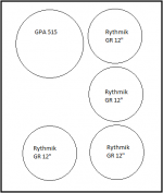
If you take 2 pairs, they can be mounted in an L-formation around the GPA/Altec 515 Alnico. I did a quick sketch in MS Paint to illustrate- see attachment (I only have Paint available, so excuse it for being basic). I know two pairs per side is getting on the expensive side, but to keep up with the quality of the other components, this is necessary IMHO. And the sound... Just what a bass freak like me wants. Enjoy,
Deon
PS. OK, I'll confess, if it was up to me, I'd take 3 pairs per side. Three drivers in the front, three in the back, all in the same L-formation (just delete the top driver in the sketch and move the GPA 515 down), with force-cancelling rods in between. A real bass nut's dream. Then again, that's just me, and I'm crazy.
Attachments
Last edited:
soongsc,
I think that a metal cone 15" driver would have a very different sonic quality than the B&C drivers that you seem to like. I personally don't like metal cones, they usually have some severe breakup modes with high Q resonances. I work with carbon fiber cones and make my own and I will say that it is not necessarily easy to make one that sound good and measures well. One of the problems that I have seen is like a metal cone driver is that it is very easy to make the cone to stiff. It is a balance that has to be made to control the material properties of the fiber content and the matrix resins.
Have you worked with the TAD TM1201(H) ?
Its "PG" cone is really special and coloration is very low. I found breakups to occur at least 1 octave above a normal paper cone of similar size (like the JBL 2020H). On the other hand the motor design is quite poor (no rings, ferrite magnet), which makes it a good candidate for current drive. The spider/suspension also looks quite intrusive as the mechanical resistance is very high (Rms=13.7), which may be part of the reasons why it seems to sound dull...
There was a lot of discussion Rms/Qms here some times (ie probably hundreds of pages...) ago...
On the subject of carbon cones and parameters "shaping", here is an interesting tease from void audio:
Void introduces new carbon models
Void introduces new carbon models
That sounds right, so I must be reading the Klippel measurements wrong..
I think it's the break-down of distortion products that I'm having problems with.
Ex. Scanspeak 18wu/4741t00
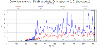
I don't really understand that plot (% THD vs. time?) so I can't comment. I am not saying that compliance can't be the highest distortion component, it depends on the signal and the situation. Was the speaker in free air, or in a small enclosure? Was there significant signal content at and below resonance?
A speaker with no air compliance operating with LFs below resonance will distort like crazy from the compliance, but its not a realistic test.
I have long argued with Klippel that his testing is only accurate where it doesn't matter. I was consulting for a company and they were using Klippel data. I asked them how stable was the data, particularly for the higher orders that matter. They didn't know. They did a "gauge capability study" and found that all orders above the third were basically random data. To quote the boss "Throw that thing out!"
- Home
- Loudspeakers
- Multi-Way
- Beyond the Ariel