Lostcause said:Barry, interesting choice of grounding point...why didn't you pick it up by the chip?
Puffin, did you remove the on-board cap?
Hello Lee, I have only broken one 2024 chip and that was trying to solder to the ground it was attached to, it cooked.

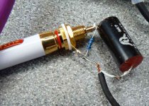
The 3 speaker wire thing is a strange one. Two speakers per channel are wired in series and the centre point between each pair is grounded by the 100uf cap in series with a 0.5uf cap.
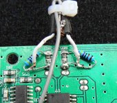
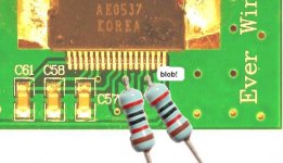
Hello Puffin, I used a 100k to ground at the input(47k is OK also) and I soldered a 47k across the 33k input resistor to give a value of 20k..Pictures are attached.
PS great work with your PS Amp Lee, I wish I could cut alloy sheet as neat, LOVERLY!!
Attachments
Audio1st. Thanks for the pics. I have not used screened cable,but I think I have connected it up correctly. It all seems to be working very well. I like the sound so far. I may change the ground resistors to 100k as this is what I used on the Sonic power amps I made. Thanks for all your help.
Are there any more improvements that could be made ? A tank cap for the power supply. I assume that the 2200uf cap is the power supply cap ?
Are there any more improvements that could be made ? A tank cap for the power supply. I assume that the 2200uf cap is the power supply cap ?
OUCHaudio1st said:
Hello Lee, I have only broken one 2024 chip and that was trying to solder to the ground it was attached to, it cooked.
The 3 speaker wire thing is a strange one. Two speakers per channel are wired in series and the centre point between each pair is grounded by the 100uf cap in series with a 0.5uf cap.[/B]
That is a strange arrangement, but if we're using other speakers I suppose we could remove those caps?
PS great work with your PS Amp Lee, I wish I could cut alloy sheet as neat, LOVERLY!!
Thanks, It took some time with a dual cutter hole saw
 but the ragged edge on the amp side made a good binding surface for the clear resin .. I just spun the lid in a drill and polished the edge up
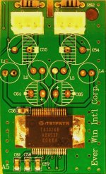
Well I've just popped her open...ahem.....and crikey this is a 'compact' implimentation! But there's been a lot of thought gone into it, some clever placement.
Those inductors are pretty useless for big drivers so they will have to go.....and so I've stripped her down to the bare essentials Some leftover aircores will go in...2 on the top & 2 on the bottom.....
need to look at the output filter components but it's very minimalistic.
My input resistors are going in right at the chip pins through those small holes....
New NIC NRSK's for power caps....
Oh yes and I've cut away all that unwanted garbage Its only 6 x 4 cm's now so two will fit into my amp and I can bi-amp my tweets and fullranges... one for left and one for right.... no crosstalk!
That will do for tonight, more fun tomorrow.....
But there's been a lot of thought gone into it, some clever placement.Those inductors are pretty useless for big drivers so they will have to go.....and so I've stripped her down to the bare essentials
Some leftover aircores will go in...2 on the top & 2 on the bottom.....need to look at the output filter components but it's very minimalistic.
My input resistors are going in right at the chip pins through those small holes....
New NIC NRSK's for power caps....
Oh yes and I've cut away all that unwanted garbage
Its only 6 x 4 cm's now so two will fit into my amp and I can bi-amp my tweets and fullranges... one for left and one for right.... no crosstalk!That will do for tonight, more fun tomorrow.....
Attachments
Lostcause. It would be really helpful if after you have finished the mods you could give us more pics and a blow by blow account (for those with v.small technical knowledge!)
I would like to see to which pins you connect the input resistors. I have some inductors left over from an S.I project where I replaced them for air-cored ones. I assume that these would be better ?
I would like to see to which pins you connect the input resistors. I have some inductors left over from an S.I project where I replaced them for air-cored ones. I assume that these would be better ?
Puffin said:Lostcause. It would be really helpful if after you have finished the mods you could give us more pics and a blow by blow account (for those with v.small technical knowledge!)
I would like to see to which pins you connect the input resistors. I have some inductors left over from an S.I project where I replaced them for air-cored ones. I assume that these would be better ?
They will go in here....top or bottom doesn't matter really.
I usually have to open up the hole a bit with my micro drills.
Put a bridging blob on the last pin to ground as well (disable sleep mode)
The rest is simple replacement exept for the filtering, need to suss it out....
Attachments
Puffin said:Lostcause. Thanks for your reply.
No problem Puffin and Yes those sonic cores will be much better than the stock inductors, they are too small and must saturate at even moderate levels, especially when we set the input to 1:1 with 20K resistors and hook them up to our main speakers.
That filter network looks OK too so not much work to do really.
Puffin said:Lostcause or Audio1st. Is the orientation of the input caps correct.
I was playing a well known CD last night and information ofr the left channel was coming out of the right. I checked my wiring and it is as shown in the picture originally posted by Audio1st.
I don't thing Barry actually meant 'L-R' to be taken litterally
But if he did then the inputs would read R-L....yes they are switched.
But never mind that....is your phase correct???
 Will you just link pins 17 & 18?
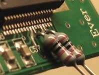
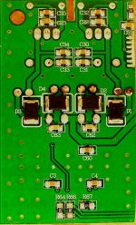
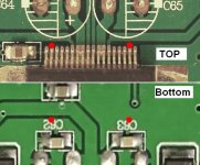
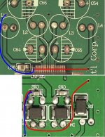
OK, so by chopping the board down I have significantly lengthened the return path to pin ground on one side so I need to put a path in there somewhere BUT when looking at the layout I see that even as it was before, the return path was very long!?
Did I say ‘clever layout’ before……
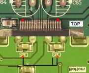
What it needs are some extra via holes, close to pins 20 and 35 so I think I’ll drill through and solder in some .7mm wire to sort this out.
Did I say ‘clever layout’ before……
What it needs are some extra via holes, close to pins 20 and 35 so I think I’ll drill through and solder in some .7mm wire to sort this out.
Attachments
audio1st said:Hi Lee, this trace will be under the chip, is that long?
Hi Barry,
It is when you look @ most other designs, the return still has to pass over the board and through a via in triangular path rather than a direct route.
Look at the decoupling path for C62.... quite long when it could be a tenth (edit: even shorter) of the path. (even longer when you chop the board up
 )
)
- Status
- This old topic is closed. If you want to reopen this topic, contact a moderator using the "Report Post" button.
- Home
- Amplifiers
- Class D
- Best value T Amp in UK ?