But it is not RussiaOdessa is even closer")
One impressive (little - MSSOP) device, missing from the datasheet -- output impedance.
I hadn't seen this application note previously -- picks up on an apnote which Jim Williams wrote some years previously: http://cds.linear.com/docs/en/application-note/an159fa.pdf
Another reason to purchase a tin of Danish butter cookies!
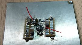
One can handle those smallish MSOPs in dead bug style. at least for a test.
In the middle is the lt3042 on its back, a "thick" wire across its belly as an
excuse for the thermal pad. The rest of the circuit is on the two square pad
strips.
OK, in the meantime I have bought a lab size vapour phase soldering machine.
WRT output impedance, I see 0.07 mV versus 199 mA delta Iload, page 6 top right.
For my oscillators in class A, I don't give a **** anyway.
And at 2 nV/sqrt Hz demonstrated, it outclasses not only other single chip
regulators but also most discrete attempts. I mean, with a AD797 / LT1028 / AD825
and its input protection resistor alone, you are already almost there; not much
left for reference, feedback resistors and maybe gain for large output voltages.
And to make the plots, it took more than a cookie box. The DUT and the preamp
were each in their own Hammond cast aluminium box, isolated from each other
and only one connection with semi rigid coax and SMA connectors. Everything ran
on NiMH cells. The whole setup was in another alu cargo box with fingerstock
across the door. Only one coax to the FFT analyzer via BNC bulkhead feedthrough.
The preamp has 20 parallel ADA4898 opamps, I have described that already on
this site.
regards, Gerhard
Attachments
Last edited:
And to make the plots, it took more than a cookie box. The DUT and the preamp
were each in their own Hammond cast aluminium box, isolated from each other
and only one connection with semi rigid coax and SMA connectors. Everything ran
on NiMH cells. The whole setup was in another alu cargo box with fingerstock
across the door. Only one coax to the FFT analyzer via BNC bulkhead feedthrough.
The preamp has 20 parallel ADA4898 opamps, I have described that already on
this site.
regards, Gerhard
A prodigious effort!
My much more prosaic setup used a single SSM2019 with 2 9V alkaline cells. At A=100 the noise was ~0.95nV/√Hz Of course, the SSM2019 is balanced input which is a very big advantage.
For oscillators I can see that noise is the most important performance contributor (and I see you are renowned in this field!!), for preamplifiers we found it was not as important as PSRR and Zout. This popped out of the particular track we used for the listening test which most likely put quite different stress on the Borbely line amps two channels, and, for the poorer performing devices, was a source of intermodulation or just muddying of the signals.
Last edited:
A prodigious effort!
My much more prosaic setup used a single SSM2019 with 2 9V alkaline cells. At A=100 the noise was ~0.95nV/√Hz Of course, the SSM2019 is balanced input which is a very big advantage.
For oscillators I can see that noise is the most important performance contributor (and I see you are renowned in this field!!), for preamplifiers we found it was not as important as PSRR and Zout.
Oohps, the real number is 180 uV for delta I = 199 mA, essentially the full range.
The 70 uV is how much it gets better when not at 120°C.
180 uV / 199 mA is 0.9 mOhm. Seems "quite ok".
PSSR is 110 db @ 1KHz falling to 80 @100 KHz. Excellent.
Personally, I'm not a friend of pushing PSSR to ultrahigh levels.
If you really make use of that, it means that you may have s***loads
of dirt half an inch from your precious clean voltage.
And if the dirt is on the board, it is everywhere.
I prefer having it reasonably clean everywhere and put the extra
effort locally where it really counts.
Gerhard
Any improvement by feeding these regs with serie very low ESR A123 LiPoFe4 cells (3.3 V by cell) ?
What would you like to improve?
The source resistance won't improve, 100 dB PSSR should be enough
for even pathological cases where the raw power is pure dirt.
Maybe some capacitance directly at the load could help, but it could
just as well impair the output noise by forming a noise peak at certain
frequencies. Look at the trace where I used 22uF at the output instead
of the 4.7 / (5*1) uF prescribed by the data sheet. Sometimes more is less.
Maybe I should test what happens with a 10,000uF wet slug tantal...
The battery might help to fight ground loops, that's why I used
a lot of NiMH cells for the measurements to power the DUT (device
under test) and the pre-amplifier.
Actually, some batteries are really good just alone, esp. fat NiCd.
I have made some measurements in
< http://www.hoffmann-hochfrequenz.de/downloads/NoiseMeasurementsOnChemicalBatteries.pdf >
I have never tested LithiumIronPhospate because I don't
have any. Maybe the 13.5V / 14AH Pb battery in my motorcycle
is the next candidate.
Gerhard
LT3042 measured
I have been playing with the LT3042 in a couple of designs now and have measured PSRR, noise and output impedance.
The measurements was conducted using a R&S UPV audio analyzer with linear technology's low noise preamp by Todd Owen and Amit Patel. This preamp is powered from li-po batteries with everything built into a mu-metal box. This way I can make measurements without 50Hz line noise
http://cds.linear.com/docs/en/application-note/an159fa.pdf

This is the board I made for it. It can be externally configured with all the options using all the connections or like here made with a fixed voltage. Ground on the two top pins and input on the left and out on the right. On this board the feedback is shorted (R7)

This shows the extremely low noise from this chip. The top curve is noise over 1 second. The lower FFT is 256k unfiltered.

This shows the output impedance. This was done by injecting 1mA on the output. (A sweep with 1V over a 1k resistor and a big capacitor)
Z out measurements are very sensitive at these low levels and just by changing the position of the measurement pin a few millimeters changes the result. On this measurement link R7 was installed, but I don't recall now if the 1k resistor and the measurement connection was connected at the output pin to the right on the picture above or if it was done closer to the chip. Probably this was done directly over the output capacitor which will give the best result.
I don't have any measurements that quantify the PSRR, but anything I have thrown at is comes out completely noise free.
The results I have from this baby are so good that I have abandoned all other regulators for my projects. I used to get the same low noise from a Salas regulator, but is not as low noise close to DC (slow fluctuations) and then it is the size and heat..
I have been playing with the LT3042 in a couple of designs now and have measured PSRR, noise and output impedance.
The measurements was conducted using a R&S UPV audio analyzer with linear technology's low noise preamp by Todd Owen and Amit Patel. This preamp is powered from li-po batteries with everything built into a mu-metal box. This way I can make measurements without 50Hz line noise
http://cds.linear.com/docs/en/application-note/an159fa.pdf
This is the board I made for it. It can be externally configured with all the options using all the connections or like here made with a fixed voltage. Ground on the two top pins and input on the left and out on the right. On this board the feedback is shorted (R7)
This shows the extremely low noise from this chip. The top curve is noise over 1 second. The lower FFT is 256k unfiltered.
This shows the output impedance. This was done by injecting 1mA on the output. (A sweep with 1V over a 1k resistor and a big capacitor)
Z out measurements are very sensitive at these low levels and just by changing the position of the measurement pin a few millimeters changes the result. On this measurement link R7 was installed, but I don't recall now if the 1k resistor and the measurement connection was connected at the output pin to the right on the picture above or if it was done closer to the chip. Probably this was done directly over the output capacitor which will give the best result.
I don't have any measurements that quantify the PSRR, but anything I have thrown at is comes out completely noise free.
The results I have from this baby are so good that I have abandoned all other regulators for my projects. I used to get the same low noise from a Salas regulator, but is not as low noise close to DC (slow fluctuations) and then it is the size and heat..
Any improvement by feeding these regs with serie very low ESR A123 LiPoFe4 cells (3.3 V by cell) ?
Short answer: No.
I have tried using low impedance Li-po batteries and the noise is exactly the same as with a sensible filtered transformer (lower than 1mV ripple). It is however easier not to pollute your measurements when using a battery.
My lab-supply has noise all over the place under 1kHz at levels up to -80dB, but the output from the LT3042 is still dead quiet.
Hi, Armand,
what did you use as the MuMetal enclosure? Is there something commercial?
I have a need for sth. like that; I have been told a price of only €60/Kg Mumetal
IIRC, but if you deform or drill it, it must be tempered again in a H2 atmosphere
and since it would require several layers that would be at least clumsy since
the isolation between the layers would melt unless taken apart again.
At least the supplier would do the annealing. But still too much ado.
I think your source impedance measurement agrees to my back-of-the-
envelope calculation from the static regulation properties in the data sheet.
A little PCB trace is easily in the mOhm range.
The rise of the noise towards higher frequencies is probably not real but the
result of the fixed FFT bin size. (absolutely more noise in more bandwidth vs.
reduction to noise density per sqrt Hz). I used the Agilent 89441A just for one
FFT per decade and combined the results of the 7 FFTs in one picture with
gnuplot and some C programming. Still one can see the change of the
noise / bandwidth at the decade boundaries.
I did also measure a few of my lab supplies, some of them are really disgusting.
< http://www.hoffmann-hochfrequenz.de...rements_On_Some_Laboratory_Power_Supplies.pdf >
regards, Gerhard
what did you use as the MuMetal enclosure? Is there something commercial?
I have a need for sth. like that; I have been told a price of only €60/Kg Mumetal
IIRC, but if you deform or drill it, it must be tempered again in a H2 atmosphere
and since it would require several layers that would be at least clumsy since
the isolation between the layers would melt
unless taken apart again.At least the supplier would do the annealing. But still too much ado.
I think your source impedance measurement agrees to my back-of-the-
envelope calculation from the static regulation properties in the data sheet.
A little PCB trace is easily in the mOhm range.
The rise of the noise towards higher frequencies is probably not real but the
result of the fixed FFT bin size. (absolutely more noise in more bandwidth vs.
reduction to noise density per sqrt Hz). I used the Agilent 89441A just for one
FFT per decade and combined the results of the 7 FFTs in one picture with
gnuplot and some C programming. Still one can see the change of the
noise / bandwidth at the decade boundaries.
I did also measure a few of my lab supplies, some of them are really disgusting.
< http://www.hoffmann-hochfrequenz.de...rements_On_Some_Laboratory_Power_Supplies.pdf >
regards, Gerhard
Last edited:
Mu-metal shielding can
Hi Gerhard,
I used these: Item # MUCAN032-232-256, MuMETAL® Shielding Cans On Magnetic Shield Corporation
It was a close fit, but I managed to get the preamp mentioned earlier and one 7,4V Li-Po battery in there for +-3.7 supply to the amplifier. +-4.2V when they are fully charged.
The amplifier had to be built with three PCB's stacked on top of each other.
The price for the can with a lid is $95 including shipping inside US. I used a separate (Norwgian) carrier from the US to Norway.


The amp is (as usual) still not 100% finished. I still have to drill two small holes for coax in and out.
The measurements was conducted with this box inside a much bigger steel cabinet grounded to the measuring instrument. Instrument grounding scheme is crucial at these low levels and it took me many iterations to find the correct setup.
Hi, Armand,
what did you use as the MuMetal enclosure? Is there something commercial?
I have a need for sth. like that; I have been told a price of only €60/Kg Mumetal
IIRC, but if you deform or drill it, it must be tempered again in a H2 atmosphere
and since it would require several layers that would be at least clumsy since
the isolation between the layers would melt
At least the supplier would do the annealing. But still too much ado.
Hi Gerhard,
I used these: Item # MUCAN032-232-256, MuMETAL® Shielding Cans On Magnetic Shield Corporation
It was a close fit, but I managed to get the preamp mentioned earlier and one 7,4V Li-Po battery in there for +-3.7 supply to the amplifier. +-4.2V when they are fully charged.
The amplifier had to be built with three PCB's stacked on top of each other.
The price for the can with a lid is $95 including shipping inside US. I used a separate (Norwgian) carrier from the US to Norway.
The amp is (as usual) still not 100% finished. I still have to drill two small holes for coax in and out.
The measurements was conducted with this box inside a much bigger steel cabinet grounded to the measuring instrument. Instrument grounding scheme is crucial at these low levels and it took me many iterations to find the correct setup.
I used to get the same low noise from a Salas regulator, but is not as low noise close to DC (slow fluctuations) and then it is the size and heat..
Hi Armand, on what version of shunt and with how large Vref filter capacitor you measured those near DC noise fluctuations? Larger Vref cap value is usually effective in the lower 1/F noise region when it matters. Lowers the overall noise a little more too.
But it takes a month to do 200 averages with a band width that fits the
start frequency of 0.1 Hz and goes to 1 MHz like my plots.
By then the DUT batteries are empty.
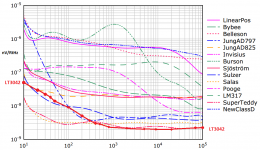
I took the data from the LT3042 to compare with a bunch of others:
Attachments
Last edited:
Nice to plot the LT3042 together with the others. But to be fair with the LT3042 you should plot the noise curve with 22uF Cset capacitor. This gives 4nV at 100Hz and 18nV at 10Hz and then matches the Salas reg. In the masurement in my earlier post I pushed the limit a little and used 47uF if I recall correctly. This is not recommended in the datasheel as it can destroy the chip during a fault condition. But I ended up on around 10nV at 10Hz.I took the data from the LT3042 to compare with a bunch of others:
Salas. I don't recall the setup. I just have a picture of the result showing around 50nV at 10Hz. A bigger cap would probably help.
It''s almost too bad that such a small and easy to use chip matches your excellent reg. It does however have it''s limitations with regards to input voltage and current. Also no negative version. And not so impressive.
My measurement with the data sheet values sees it at 10-12 dB above 1nV/sqrt Hz.
That's about 3.5 nV/sqrt Hz @ 10 Hz.
And the preamp is already at 1nV +8 dB because it has only 200 uF foil
capacitors at the input and that does not short the thermal noise of the
bias resistor good enough at 10 Hz.
The preamp itself is at 6 dB below 1nV @ 10 Hz. I already have 4700uF wet slug
tantalums to put that straight.
(and a solution with parallel IF3602s that can stay with foil caps.)
< https://www.flickr.com/photos/137684711@N07/24070698809/in/album-72157662535945536/ >
all measured under same conditions as shown by their data sheets.
Reference is decoupled where applicable.
Gerhard
Last edited:
I took the data from the LT3042 to compare with a bunch of others:
It seems the voltage scale is somewhat weird?
- Status
- This old topic is closed. If you want to reopen this topic, contact a moderator using the "Report Post" button.
- Home
- Amplifiers
- Power Supplies
- Best low noise regulator?