amplifierguru said:Hi Jorge,
As soon as my website's up and running.....
Hi Kanwar,
Favourite chip - easy - OPA637 (x5 decomp) It just has such a good balance. can you make them in India.
PS You're not flooded out are you?
Cheers,
Greg
Hello Greg,
They[opa637] are very easily available in INDIA in NEW DELHI....
OUR state is 1500 KMS far from the Flooded areas....yet safe
Kanwar
jcx said:Charles, you are truly amazing
Aw shucks, you are too kind!
Eva said:The output impedance of an emitter follower is the output impedance of the previous stage divided by the instantaneous current gain, plus that 26/Ie component due to Vbe changes.
To avoid going OT:
Let's say the thread starter would choose MOSFET driver's for the MJ15024/25's (something John Curl does AFAIK)
Is there any analogy to calculate easily output impedance, when the circuit contains FET's (ie source followers)?
And source follower double stage, in cas of MOSFET's?Charles Hansen said:Again, yes. I take this for granted, but this is where many, many audio amplifiers fall on their face. An emitter follower double output stage does not have enough current gain to avoid creating high levels of distortion, yet this is what most audio power amps use.
Thanks, Tino
zinsula said:Is there any analogy to calculate easily output impedance, when the circuit contains FET's (ie source followers)?
And source follower double stage, in cas of MOSFET's?
One interesting output stage is to use source followers driving emitter followers. The easiest way to calculate the output impedance of the source follower is to use the data sheet. Usually there is a graph of transconductance versus drain current. The output impedance is the reciprocal of the transconductance. (The transconductance is proportional to the square of the drain current, which is why FETs are sometimes called "square law" devices.)
It's not too hard to use driver FETs that have an output impedance of a few ohms. When using an output emitter follower with a beta of 100 (typical for modern output devices), this contributes a few tens of milliohms to the output impedance of the open-loop circuit.
If you are using source follower outputs, you may not even need a driver stage. Unlike bipolars, the output impedance of a source follower is not affected by the output impedance of the driving stage. However the frequency response will be, as there is a relatively large input capacitance that you have to worry about.
Charles Hansen said:Again, yes. I take this for granted, but this is where many, many audio amplifiers fall on their face. An emitter follower double output stage does not have enough current gain to avoid creating high levels of distortion, yet this is what most audio power amps use. Then the designer relies on negative feedback (as a crutch) to clean up the mess he has made with his bad circuit design. (Using a CFP in the output stage does not solve this problem.)
Mr Hansen,
What do you call a "emitter follower double output"? A darlington, or 2 paralleled emitter followers?
Charles Hansen said:(The transconductance is proportional to the square of the drain current, which is why FETs are sometimes called "square law" devices.)
For MOSFETs, Id is proportional to the square of the difference between Vgs and the threshold voltage. To get transconductance, take the derivative of Id with respect to Vgs. This is proportional to the difference between Vgs and the threshold voltage. Thus transconductance is proportional to the square root of the drain current.
SY said:CH: How "ideal" is that input capacitance?
Very ideal. Ever heard about varactors?

Jorge said:
Very ideal. Ever heard about varactors?
Yes indeed. Everything is ideal compared to varactors.
SY said:CH: How "ideal" is that input capacitance?
Not very ideal at all. The input capacitance rises as Vds drops (ie, near clipping). This problem is *much* worse with vertical MOSFETs than either lateral MOSFETs or JFETs.
Bricolo said:What do you call a "emitter follower double output"? A darlington, or 2 paralleled emitter followers?
I mean an emitter follower driving another emitter follower. This is basically a Darlington, although there are variations in where to connect the emitter of the first follower.
Paralleling two emitter followers does not increase the current gain. Instead you are essentially creating a composite transistor with twice the current capacity and twice the maximum power dissipation.
andy_c said:For MOSFETs, Id is proportional to the square of the difference between Vgs and the threshold voltage. To get transconductance, take the derivative of Id with respect to Vgs. This is proportional to the difference between Vgs and the threshold voltage. Thus transconductance is proportional to the square root of the drain current.
You are exactly right -- thanks for the correction Andy. (Unlike my posts, I don't think Andy makes mistakes!)
SY said:
Yes indeed. Everything is ideal compared to varactors.
Serious now - the gate capacitance near VDS=VGS behaves like a varactor for the more common MOSFETs (IRF, etc).
That's one of the tricky aspects of switching power supplies design.
Jorge said:the gate capacitance near VDS=VGS behaves like a varactor for the more common MOSFETs (IRF, etc)
Yes, these are the vertical MOSFETs that (in my opinion) are not well suited for audio use.
Charles Hansen said:
Yes, these are the vertical MOSFETs that (in my opinion) are not well suited for audio use.
Hi Charles Hansen,
I absolutely donot agree with you..
I think you are not aware of the advantages offered by vertical Mosfets in audio amps...maybe you donot have tried your hands on building amps especially with n-channel mosfets only at output..
regards,
Kanwar
Workhorse said:
Hi Charles Hansen,
I absolutely donot agree with you..
I think you are not aware of the advantages offered by vertical Mosfets in audio amps...maybe you donot have tried your hands on building amps especially with n-channel mosfets only at output..
regards,
Kanwar
http://www.diyaudio.com/forums/showthread.php?postid=333756#post333756 http://www.diyaudio.com/forums/showthread.php?postid=334963#post334963

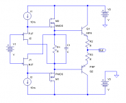
bocka said:I build something similar. The "Fetlington" works fine. I've tested it with and without the cap across the driver source resistor. No measurable difference. The follower works up to 500kHz until cross conduction occurs.
Very cool! Thanks for that info.
- Status
- This old topic is closed. If you want to reopen this topic, contact a moderator using the "Report Post" button.
- Home
- Amplifiers
- Solid State
- Best driver for MJ15024/25 motorola transistor