Have you seen the parallel Thread discussing Linear PSU?
This one?
http://www.diyaudio.com/forums/power-supplies/102277-dedicated-psu-deq-dcx2496.html
Anyone have experience with that? Looks good to me.
One of the reasons I went for a bigger box, so it was easier to work with for future upgrades.
Your approach rings some bells. I would love to hear more details as well as the bigger picture.
There really was no grand philosophy, just an urge to sort out the levels problem without spending any cash! ")
I haven't gone into too much detail because my implementation is so specifically based around bits from my junkpile that it wouldn't really be relevant to anyone else. The new case came from the same 1990's vintage JBL system controller that provided the output traffos, and the inputs came from a 80's Amek studio desk. Not the bits your average diy'er has to hand.
I haven't gone into too much detail because my implementation is so specifically based around bits from my junkpile that it wouldn't really be relevant to anyone else. The new case came from the same 1990's vintage JBL system controller that provided the output traffos, and the inputs came from a 80's Amek studio desk. Not the bits your average diy'er has to hand.
There really was no grand philosophy, just an urge to sort out the levels problem without spending any cash!
I haven't gone into too much detail because my implementation is so specifically based around bits from my junkpile that it wouldn't really be relevant to anyone else. The new case came from the same 1990's vintage JBL system controller that provided the output traffos, and the inputs came from a 80's Amek studio desk. Not the bits your average diy'er has to hand.
Actually I was asking more basic things, like the box finally is used as an active crossover only? getting input from pre? and feeding two amps? (which is my case hence my interest)
Yup, input from a preamp, then outputs go to six power amps, exactly as it was designed to be used.
Speechless, perhaps exactly as it was designed to be used.
Seriously though, my task is rather basic i.e. to split between an SE 845 and active subs.
In this case would you advise the same route (Bery) or a more simplistic aproach? and which one ?
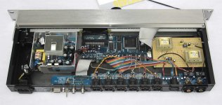
Thanks for the photo, PM. Nice work! Interesting to see how you moved stuff around.Here's my version with "found" traffos and transplanted into a bigger box:
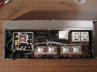
Below is a photo of a DCX I modified for a friend. Unlike my own DCX, this one has the output transformers external, at the amps. The output transformers are the rather large Cinemag models.
The outputs go from the DAC chips to the XLR connectors via a 220R resistor in each leg. You will notice that the XLR connectors are flipped. This allows me to use them, while keeping the PCB underneath. Signal is run via balanced mic cable to the transformer at the amp itself. This approach allows great flexibility because you have the direct output of the DAC right on the rear panel. With that, you can use any output topology you decide on, now or in the future.
The analog inputs are via RCA and have an opamp buffer in front of the input transformers. None of the original input circuitry was used. Input C was kept stock.
Digital input now come in via 2 RCA connectors on the rear panel. There is a toggle switch to select one or the other. Works like a charm. The RS232 connection is left intact.
I replaced a lot of the small, cheap electrolytic caps with Panasonic FM series caps of the same physical size, but higher value. This was done near the voltage regulators and at all the DAC and ADC chips. I tested to be sure that all was stable with the new, bigger, lower ESR caps. It is.
A fairly straight forward modification that really works well.
Attachments
Below is a photo of a DCX I modified for a friend. Unlike my own DCX, this one has the output transformers external, at the amps.
Is he using input transformers or is he using what are designed to be output transformers as input transformers?
In this case would you advise the same route (Bery) or a more simplistic aproach? and which one ?
Sorry, I'm not sure I understand your question. You can't drive the DCX from a power amp.
The Jensen JT-11 DMPC just fits inside the enclosure. Take the signal right off the D/A pins, now you have isolated/balanced outputs with ridiculously low distortion, well below 20 Hz. These are bifilar wound output transformers.
I added some RF chokes on each input leg, and a ferrite bead as common mode filter to reduce any RF hash that might want to push through the high interwinding capacitance.
Feeds an active 6-channel volume control. Very happy.
I added some RF chokes on each input leg, and a ferrite bead as common mode filter to reduce any RF hash that might want to push through the high interwinding capacitance.
Feeds an active 6-channel volume control. Very happy.
Attachments
Those are 1:1 transformers. As to the subtleties of what makes a 1:1 transformer work better in one direction than in another, you'll have to ask a winder, not me - I don't have a clue.Is he using input transformers or is he using what are designed to be output transformers as input transformers?
Basically they are working from a low impedance source (opamp buffer) into about a 4K load, as they were designed to do.
Nicely done!The Jensen JT-11 DMPC just fits inside the enclosure.
Pano:
I think what SY is asking is did he use a xfmr designed as an output xfmr and apply it as an input xfmr.
http://www.jensentransformers.com/an/an002.pdf
For example, using the Jensens as I have makes for a really good output xfmr to drive a set of cables and an amp at the far end. This same xfmr would make a really poor input xfmr installed right at an amplifier's input.
The converse is true for a genuine input xfmr.
I don't know. The transformers used on the input here were specified as output transformers by me for use in the DCX. They were built by BudP of Onectics. They were meant to drive a medium impedance load from a low impedance source.
I talked with Bud about the difference between input and output transformers and, IIRC, he plead ignorance. As long as the source and destination impedances are known, what difference does it make to a 1:1 transformer? If a transformer is inside a unit sandwiched between an opamp driver and a low input impedance chip, what is needed?
I've tested these particular transformers backwards and forwards, high to low, low to high, low to low, high to high. As long as they have a reasonable load on the primary, I can't find any significant difference in performance.
So I don't really understand the difference, at least in short line applications. Maybe someone with more transformer savy can shine a light on the subject. I'm all ears!
The audio transformer manufacturers tell us repeatedly that input and output versions are different. They further tell us that they should not be installed in reverse orientation.
Why should we doubt their statements as other than fact.
Not because it sells more of their product.
Why should we doubt their statements as other than fact.
Not because it sells more of their product.
So I don't really understand the difference, at least in short line applications. Maybe someone with more transformer savvy can shine a light on the subject. I'm all ears!
Check the Jensen app note that zigzagflux linked.

- Home
- Source & Line
- Digital Line Level
- Behringer DCX2496 digital X-over