OK Using the 120Hz test tone on a stick and max volume on the player I measured .944VMRS input to the output Bd. and 3.67VRMS at the XLR.
Changed feed back resister on the 1st stage to 37Kohms and measured 8.70VRMS out of the XLR.
Changed the feed back resistor to 57K for more head room and and it works great.
With the test tone it maxs out at 12VRMS at about 3/4 volume and with regular music it clips the input to the DCX at about 3/4 volume.
I think I have a good match now without an extra box. (-:
Andy
There's a thread over on lab section of AA about a "mystery DAC" & fixing it's horrific SPDIF input stage. Although not stated what the make/model of this DAC is, it is said to start with "B" & has two large ferrites on each leg of the SPDIF input transformer (? make) & then a CS8420 SPDIF receiver. Does this describe the Behringer SPDIF input stage?
Very intersting discussion about the DCX, Thanks to all of you!
Now i have a problem with one of my Dac-Chip in my DCX.
Does anybody know, where i can buy the original Chip and which size it is? i want to repair it by changing the chip, that produces the noise.
The Dac-Chip i mean, is the AKM AK 4393. I am not sure about the size.
Appreciate for all infos!
Greetings
Rainer
Frank Oettle Module + Guido Tent Clock. Benefits?
Hi Ergo,
one question about your set up of the Frank Oettle Digital Input Module.
First you implemented the Guido Tent Clock and you removed Q3+C76+C77, R34, and you cut after R30B, so by the Guido Tent Clock a stable and low jitter CLK24 and ACLK12 was available. The problems around the 8420 were not taken in account.
What did you really do when you implemented the Frank Oettle Module? Did you installed again Q3+C76+C77 and R34 so the CLK24 coming from the DSP board was used again? I ask this because from the pictures of your History seems that the Frank Oettle module is installed keeping Q3+C76+C77 and R34 not installed.
Have you never tried the Frank Oettle Module to solve the problems of the 8420, plus the Guido Tent Clock to have a low jitter CLK24/ACLK12 to use in the ADCs 5383 and in the DACs 4393?
If the matter is already discussed in another thread please let me know.
If there are some mistakes in my way please help me to understand where.
I don't like to copy only.
Thanks and regards.
Mario Canever
Frank's board includes low jitter clock, and in order to function one crystal has to be removed and few resistors as I recall. I did not made mod with Tent's clock so I do not know what needs to be removed for that, but my assumption is that you would need to remove that clock and not reinstall old parts. Frank's board uses CS8416, so the problem with CS8420 is gone, if that is what you asked.
I taught this article might be of big interest for many. This subject was digested here over and over, how to convert S/PDIF to AES/EBU and vice versa. Here you will find very good info. This was posted in another thread, and I think it will be helpfull read here as well.
Interfacing AES3 & S/PDIF
Interfacing AES3 & S/PDIF
Hi AR2, thanks for your attention. Fully agree with you.
I want to explain better my dubt.
The Frank Oettle input solution use an on-board clock and manage very well the jitter caused by the SPDIF/AES cable (and, top important, manage the 192KHz/24bit).

The Frank board use, of course, also the CLK24 that it is the master clock of DCX (pin 9 on the CS8420). This master clock of the DCX is generated in the simplest way by a crystal plus 2 capacitors and a resitor, inverted and bla bla bla. So this master clock isn't cared about the jitter, the PSU, its a basic clock.
If I want the CLK24 DCX master clock with the lowest jitter possible, I have to implement another clock like described here horloge de reclocking numérique pour Behringer DCX2496 or here XO (or its special version described by Ergo DIYaudio by Ergo with care also to the ACLK12 ... 2 frequencies generated) or another of the low jitter clocks available on the web.
Is it right what I am saying? And, more important, does it have sense? Better, can be eared the difference of a clean/stable DCX Master Clock?
I don't see any way to extract the CLK24 from the Frank board. Right?
.... sorry for my so so english.
Ciao.
I want to explain better my dubt.
The Frank Oettle input solution use an on-board clock and manage very well the jitter caused by the SPDIF/AES cable (and, top important, manage the 192KHz/24bit).
The Frank board use, of course, also the CLK24 that it is the master clock of DCX (pin 9 on the CS8420). This master clock of the DCX is generated in the simplest way by a crystal plus 2 capacitors and a resitor, inverted and bla bla bla. So this master clock isn't cared about the jitter, the PSU, its a basic clock.
If I want the CLK24 DCX master clock with the lowest jitter possible, I have to implement another clock like described here horloge de reclocking numérique pour Behringer DCX2496 or here XO (or its special version described by Ergo DIYaudio by Ergo with care also to the ACLK12 ... 2 frequencies generated) or another of the low jitter clocks available on the web.
Is it right what I am saying? And, more important, does it have sense? Better, can be eared the difference of a clean/stable DCX Master Clock?
I don't see any way to extract the CLK24 from the Frank board. Right?
.... sorry for my so so english.
Ciao.
HI again, after checked and checked again I found the reply by Frank Oettle, 12th June 2010, 01:32 PM, #2734 with his helpful summary DCX table.doc.
To have the input 192KHz managed, very low jitter, PLUS the main clock of the DCX2496, i.e.: CLK24, jitter "free" there is Frank board SRC v1.0 produced by Pilgham Audio.
All the other solutions to care both things need 2 boards, one to manage the input and one for the master clock CLK24, but always with a 10 cm cable and a higher jitter (even if only a little for Guido Tent).
@Frank Oettle: on the Pilgham Audio solution there a red wire saw in the picture of the DCX board. What's this wire? Do you bring the CLK24 in the middle of the board for a better distribution? or what else?
Ciao
")
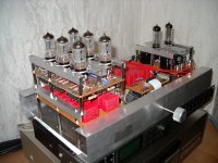
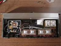
Hi Steve,
it is an full ballanced outputstage with volumecontrol for the DCX. It has 12 separat "preamplines" for all 6 outputchannels.
The original Input/Output board from the DCX isn´t in use anymore. The input is via S/P-DIF - through DAC - after DAC volumecontrol - and at the end tubevalves.
Greetings
Rainer
How/where to solder wires for balanced signal from DACs?
Greetings! Great thread, but WHEW is it long! I have a DCX2496 and 3 pairs of transformers, with each pair optimized for one band (bass, mid, HF). They are designed to take the balanced output straight from the DACs, output SE, and completely bypass the stock output section.
I've built some tube gear but I couldn't be any greener about sticking a soldering iron onto a board with SMDs. Would someone be so kind as to point me to the easiest point on the board to pull out the +/- LR signals straight from the DACs? I found a great photos on Lampizator's site that shows exactly this for the SRC2496, but have failed to find the same for the DCX. I read the great article by Jan Diddens, “Greening the …” (http://www.audioxpress.com/magsdirx/ax/addenda/media/didden2657.pdf) and admire how he used a new connector to tap into that header, but I ONLY want to pull out the balanced analog signal. What is the best (easiest) way to do it?
From the schematic it looks like the DAC pins are 20-23, and these match up to 13-16 (DAC 1), 17-20 (DAC 2), and 21-24 (DAC 3) on the connector. What I think would be really slick is some connector to plug between male and female connectors that is designed to permit an access point – but I’m probably dreaming.
Last edited:
Cut into the ribbon
I just use the individual wires of the ribbon cable which is the largest one. It's very easy to peal them apart after starting a small slit with a razor knife. Leave the pairs stuck together and twist them on the way over to the transformers. Starting from the red wire,(which is the opposite way of counting compared to the schematic) channel 6- is the third. Channel 1+ is the 14th.
.
.
Greetings! Great thread, but WHEW is it long! I have a DCX2496 and 3 pairs of transformers, with each pair optimized for one band (bass, mid, HF). They are designed to take the balanced output straight from the DACs, output SE, and completely bypass the stock output section.
I've built some tube gear but I couldn't be any greener about sticking a soldering iron onto a board with SMDs. Would someone be so kind as to point me to the easiest point on the board to pull out the +/- LR signals straight from the DACs? I found a great photos on Lampizator's site that shows exactly this for the SRC2496, but have failed to find the same for the DCX. I read the great article by Jan Diddens, “Greening the …” (http://www.audioxpress.com/magsdirx/ax/addenda/media/didden2657.pdf) and admire how he used a new connector to tap into that header, but I ONLY want to pull out the balanced analog signal. What is the best (easiest) way to do it?
From the schematic it looks like the DAC pins are 20-23, and these match up to 13-16 (DAC 1), 17-20 (DAC 2), and 21-24 (DAC 3) on the connector. What I think would be really slick is some connector to plug between male and female connectors that is designed to permit an access point – but I’m probably dreaming.
I just use the individual wires of the ribbon cable which is the largest one. It's very easy to peal them apart after starting a small slit with a razor knife. Leave the pairs stuck together and twist them on the way over to the transformers. Starting from the red wire,(which is the opposite way of counting compared to the schematic) channel 6- is the third. Channel 1+ is the 14th.
.
.
Agree, your best bet is tapping into the ribbon cable. Another way of doing it, if you will house transformers in a different housing, is to cut XLR connectors from the board and than run wires from the ribbon to it. That way you send the signal through the XLR to the next stage.
I just use the individual wires of the ribbon cable which is the largest one. It's very easy to peal them apart after starting a small slit with a razor knife.
Wow, you guys are great with the help! I looked again and figured y'all would say to use the 2K resistor point for each leg, on the output board. But using the ribbon cable seems better over the long haul.
So you are cutting the ribbon cable wires from the connector? Do you just cut the 12 you need and leave the rest plugged in?
Using the ribbon seems a LOT easier, though not reversible. Sometimes it's good to commit to mods... and not look back.
Yes that is exactly what you do, cut wires that you need and leave the rest intact. Leftover wires are needed since they carry input signals and control signal to the DB25 connector. If you make mistake, that ribbon cable with connectors is easy to purchase, ether assembled or in parts.
I think this is what you were interested in?
I use toslink input instead of straight SPDIF, but other than that we sound the same.
Amazingly low distortion with this setup, and fully balanced.
And I take it out of case to this, what I just redid in the new housing:
http://www.diyaudio.com/forums/pass-labs/186848-babelfishing-mighty-ar2.html#post2541235
- Home
- Source & Line
- Digital Line Level
- Behringer DCX2496 digital X-over