The problem is that the DCX is basically a pro-audio positioned piece of equipment. Pro audio input and output levels are up to 14dB higher than home audio equipment. So if you mod your player, you have to keep on modding any other source you'll be using.
The output level is also too high so you'll have to turn it down more than ususal, and hopefully you don't overload your preamp/level control.
To use the DCX in an easy and flexible way in home hifi there's a lot to say for modding the DCX rather than the rest of your system.
Jan;
Thanks for your input. This system is a dedicated PA sound system for outdoor pyromusicals. The player will be the only source ever and the outputs will drive QSC amps. The only missmatch I have is with the player. With this applicashoin I think it best to mod the player not the DXC. I could use a level converter but would rather not have another box on a portible system.
Any thoughts on modding the CDMP-1400 player?
Andy
Yes of course, depends on the app. Just wanted to give my 2eurocents.
I don't know that player, but a schematic of the post DAC analog part should make it clear if/how that gain can be increased. Do you have any?
jan didden
Improve crosstalk on active output mod
Hi,
Over on the DCX yahoo forum I was discussing strange cross talk measurement result when measuring the DCX2496 (see also request of Jan some posts ago) with the acitve output mod from Jan
As it turns out, the lowered crosstalk is caused by the last low pass filter stage after the DAC (on the active outputboard). This filter stage can be easily removed by removing C29 to C31, and bypassing R45 to R50.
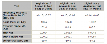
Results without low pass filter removed:
Test</STRONG>Digital Out / Analog in (out 1&2) @ 96kHzDigital Out / Analog in (out 3&4) @ 96kHzDigital Out / Analog in (out 5&6) @ 96kHzFrequency response (from 40 Hz to 15 kHz), dB:+0.10, -0.07+0.13, -0.08+0.14, -0.08Noise level, dB (A):-102.2-102.8-103.2Dynamic range, dB (A):102.0102.4103.0THD, %:0.00540.00530.0048IMD + Noise, %:0.00920.00910.0089Stereo crosstalk, dB:-59.8-59.6-59.6
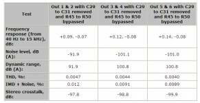
Results with low pass filter removed:
Test</STRONG>Out 1 & 2 with C29 to C31 removed and R45 to R50 bypassedOut 3 & 4 with C29 to C31 removed and R45 to R50 bypassedOut 5 & 6 with C29 to C31 removed and R45 to R50 bypassedFrequency response (from 40 Hz to 15 kHz), dB:+0.09, -0.07+0.12, -0.08+0.14, -0.08Noise level, dB (A):-91.9-101.1-101.0Dynamic range, dB (A):91.9100.8100.8THD, %:0.00470.00440.0040IMD + Noise, %:0.0120.00910.0089Stereo crosstalk, dB:-97.8-98.8-99.9
This makes stereo image even better. Definitely worth a try!
P.S: don't mind the lower noise rating of out 1 & 2, probably some test wires were picking up some noise.
Hi,
Over on the DCX yahoo forum I was discussing strange cross talk measurement result when measuring the DCX2496 (see also request of Jan some posts ago) with the acitve output mod from Jan
As it turns out, the lowered crosstalk is caused by the last low pass filter stage after the DAC (on the active outputboard). This filter stage can be easily removed by removing C29 to C31, and bypassing R45 to R50.
Results without low pass filter removed:
Test</STRONG>Digital Out / Analog in (out 1&2) @ 96kHzDigital Out / Analog in (out 3&4) @ 96kHzDigital Out / Analog in (out 5&6) @ 96kHzFrequency response (from 40 Hz to 15 kHz), dB:+0.10, -0.07+0.13, -0.08+0.14, -0.08Noise level, dB (A):-102.2-102.8-103.2Dynamic range, dB (A):102.0102.4103.0THD, %:0.00540.00530.0048IMD + Noise, %:0.00920.00910.0089Stereo crosstalk, dB:-59.8-59.6-59.6
Results with low pass filter removed:
Test</STRONG>Out 1 & 2 with C29 to C31 removed and R45 to R50 bypassedOut 3 & 4 with C29 to C31 removed and R45 to R50 bypassedOut 5 & 6 with C29 to C31 removed and R45 to R50 bypassedFrequency response (from 40 Hz to 15 kHz), dB:+0.09, -0.07+0.12, -0.08+0.14, -0.08Noise level, dB (A):-91.9-101.1-101.0Dynamic range, dB (A):91.9100.8100.8THD, %:0.00470.00440.0040IMD + Noise, %:0.0120.00910.0089Stereo crosstalk, dB:-97.8-98.8-99.9
This makes stereo image even better. Definitely worth a try!
P.S: don't mind the lower noise rating of out 1 & 2, probably some test wires were picking up some noise.
Attachments
Last edited:
+/- 12 VDCWhat are the supply voltages to the output opamps?
.15 VRMS into the output Section and .3 VRMS outWhat is your existing maximum Vpk from the player?
+-12Vdc as the supply will limit your maximum peak output voltage to ~10Vpk if the loading is light.
Are you confirming that the peak output voltage of the player is 0.3Vrms ~ 0.424Vpk?
But if 0.3Vrms is an average reading or meter scaled to read out rms from an average then it is not the peak output of the player, unless you feed in a fixed test voltage and adjust the test signal until the output shows signs of clipping.
Andrew; The 0.3 VRMS was measured using pink noise and a DVM. The unit has a Output Level speck of "2.0 +/- 0.2V R.M.S." What ever that means?+-12Vdc as the supply will limit your maximum peak output voltage to ~10Vpk if the loading is light.
Are you confirming that the peak output voltage of the player is 0.3Vrms ~ 0.424Vpk?
But if 0.3Vrms is an average reading or meter scaled to read out rms from an average then it is not the peak output of the player, unless you feed in a fixed test voltage and adjust the test signal until the output shows signs of clipping.
But I should be able to get 1.23 VRMS out of it.
Andy
Witch Question? I posted my question some time back but no one responded. AndyThis appears to be the same question that was asked and answered a couple of weeks ago.
I have a second
Looks like it is happening often - the frozen display and LEDs. This really makes it difficult for those DIY-ers who modify - the mods void the warranty, and the mods could be costly too specially if the DCX freezes on you.
Very strange. Maybe it's sunspots? In all the years I've used my DCX it's never been any trouble. But today? Frozen. No controls worked at all, nothing. Powered down and back up and it's fine. Weird. Are the talking to each other?
Very strange. Maybe it's sunspots? In all the years I've used my DCX it's never been any trouble. But today? Frozen. No controls worked at all, nothing. Powered down and back up and it's fine. Weird. Are the talking to each other?
I hear you. Every time I switch on I keep fingers crossed ... Noticed that the DCX freezes when switching from cold ( i.e. overnight); powering back up brings it to life. Thinking to keep it on 24/7. But the main problem is that I don't dare to apply the mods which I already have (Frank's src/clock) since I don't know if (or when) this one will freeze permanently

I know people say that this is cheap unit (but all is relative); however the unit freezing up (and not working) , and not working to the "audiophile" standards are two different things. I would expect that even the cheap unit (again:all is relative) to at least operate. If it doesn't work at all, then it is very expensive ..
Last edited:
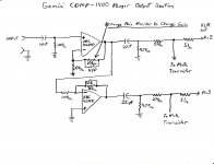
Jan; Here is the output Section of the CDMP-1400 player and what I think will change the gain. Andy
Yes that will change the gain. Strange though that you only have .3V or so. It is configured for gain of two and if the DAC is a voltage-out DAC that should be enough for several volts.
You should measure the max output level with a CD with known max level of a sine wave. You can probaby burn one yourself.
jan didden
- Home
- Source & Line
- Digital Line Level
- Behringer DCX2496 digital X-over