steviejoe said:any others designed for the beginner.
Rod Elliot's ESP site is just about a complete book on constructing pre's and power amplifiers.
Better make that 2 books, the effort Mr Elliot has invested in it is impressive.
(not the absolute truth in every aspect imo, but it is a unique compilation of practical and theoretical ampy stuff)
Vince,
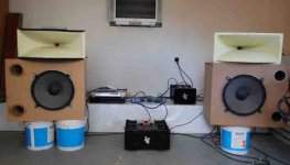
from the picture you posted it looks like you will have to move to a bigger apartment in the banlieu for the next project.
Hey Guys,
I now have spent some time to listen to it, and even took time to set the AC gain following NP's method...
But I would have a question for people that have already built this A:
I used a CrCrC in PSU , a 2x21 V transformer on rails with 2 channels working I get +/- 26v
and I used a 47.5K resistor to set the bias...(with brian GT cards)
actually the resistors in the CRC , that are 0.1Ohm gets very hot (I used 25Watts )resistors ... put a voltmeter across them and got 0.493V so I guess the total curent is 4.93Amps
this would make about 5 Amps on each rail when amp is running the 2 channels...this seem a lot to me, but in your experience is that ok? and reaching the wanted figures?
also each fet has about 0.380v on it's source resistor (0.47R)
that is to say 800 mA ...
I think that is just fine, but I don't remember if the goal is 500ma instead of 800mA , should I lower to 500??
actually nothing is getting too hot, you can put your finger on each fet for about 8sec max after one hour ...and heatsinks are about 15 degC after 1 hour...(15deg above room temp..)
actually only the R from the CRCRC are really hot (you can put finger on it max 1 second after 10minutes ... also the transformer is getting hot too...
any advise would be welcome!
Vince
Banned
Joined 2002
bobsinclar said:No news is good newsso I guess as no one responded to my question that these figures are ok
Vince
The resistor should get warm as it is pulling current through it all the time. The tranny should also get warm but not hot. If it is hot id swap it out and get a higher va one.
Jase
bobsinclar said:No news is good news
Vince
I hope that you have many holes in bottom and cover plates
btw-where power resistors in CRC filter are physically located?
Chocky, sure holes are necessary! hot in there afret 4 hours of work...
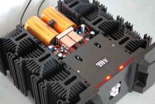
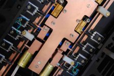
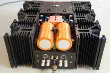
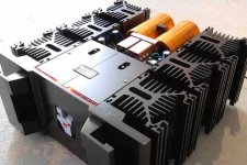
I am afraid the crc resistors are not well located, they are exactly under the 4 (blue ) psu caps... so their heat is just warming them up (althought they are rated 85 to 100°c I think this will lower their lives...
you can see just xwhere they are looking at the picts I posted, I posted the >PSU module (4 blue caps screxed on a copper plate with the resistors going from a cap to another...
do you think this can be a problem?
I actually thought that 0.1R wouldn't heat that much, this is why I put them so close from the caps...but 5 amps on each rail is tremendous
Vince
bobsinclar said:Chocky, sure holes are necessary! hot in there afret 4 hours of work...
I am afraid the crc resistors are not well located, they are exactly under the 4 (blue ) psu caps... so their heat is just warming them up (althought they are rated 85 to 100°c I think this will lower their lives...
you can see just xwhere they are looking at the picts I posted, I posted the >PSU module (4 blue caps screxed on a copper plate with the resistors going from a cap to another...
do you think this can be a problem?
I actually thought that 0.1R wouldn't heat that much, this is why I put them so close from the caps...but 5 amps on each rail is tremendous
Vince
yup ,and that's just 5 Watts in dissipation .....
if you can-relocate them on main heatsinks
bobsinclar said:the crc resistors are not well located
Vince,
suggestion:
why not turn the Welwyn resistors upside down and connect them to the copper PS ground with another strip of copper ?
(probably means you'll have to remove one of the Welwyn's mounting flanges, isolation value of the Welwyns is over 1000V )
Your resistors are good for a little over 5 watts without a heatsink, they only need a small heatsink area to drop their temperature considerably.
that is to say 800 mA
800mA times 3 = 2.4 amps (*2 ~ 5 amps)
This is SE, the bias needs to be at least as high as the peak output current.
At 500mA bias per device the output power wil be kind of weeny for such a big amplifier.

Above 1 amp bias per device would be cooler and hotter, with the heatsink temperature you posted you might be able to reach as high as 1.3 amp per device for acceptable heatsink and die temperatures.
Banned
Joined 2002
Hello!
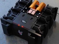
No actually the leds are for music level... as bias is quite constant, I thought it would swing more if it was moving with music...but first place I wanted it to indicate bias...
sure I used B GT boards, but I customed them a bit... adding 2200 mfcaps and 47mf caps on supply close to the small fetts
I also fitted them with big copper heatsinks...
Vince
Banned
Joined 2002
bobsinclar said:Hello!
No actually the leds are for music level... as bias is quite constant, I thought it would swing more if it was moving with music...but first place I wanted it to indicate bias...
sure I used B GT boards, but I customed them a bit... adding 2200 mfcaps and 47mf caps on supply close to the small fetts
I also fitted them with big copper heatsinks...
Vince
I see that. I know my boards when they pop out and look at me
great job..The led array reminds me of the one on the Phaselinear 400 amp i used to have
( i miss that am
)- Status
- This old topic is closed. If you want to reopen this topic, contact a moderator using the "Report Post" button.
- Home
- Amplifiers
- Pass Labs
- Beginning my aleph 30