Dear Andrew,
I am completely newbie on amp/audio circuits. Some times even I don't understand technical words like feedback/zobel network/star earth ground bla bla. So as per your reply PSU is ok except c5 and c6. Can I through that amp and start build own amp form National semiconductor or form this DAN reference circuit. Which one is good ?. Speakers have efficiency 85.5dB 8ohm.
Thanks,
Nag.
To that, I would have to ask, what power voltage have you planned to use?
Dear Andrew and members,remove S1 & S2 Fuses here need to be so big to survive start up that they offer no safety advanatge when something goes wrong. A close rated mains fuse is far better at giving the required safety.
remove C5 & C6. They are more likely to increase ringing on the supply lines.
They cannot offer lower impedance seen from the amplifier because they are too far away. Local Supply Rail Decoupling has to be LOCAL to where the currents change.This sch is completely ****** up. Is that an interpretation of what Daniel is giving you?
Go back to the datasheet from National and start with that.
Then add in filters at the input and Thiele Network at the output and proper Local Supply Rail Decoupling.
Now I am going to build with official schematic, Please let me know what changes need to done like capacitors/resistors. and any modifications or valuable suggestions.


Last edited:
add an RF filter to the input.
Change C2 to 100uF
Make sure that R1, R2 and C2 connect to input signal return.
Why is 2200uF fitted to output? It has no C number ! Did you add it to the sch?
I added 2200uF as per previous suggestions as protection to speaker.
I didn't get you exactly "add an RF filter to the input"
I didn't get you exactly "Make sure that R1, R2 and C2 connect to input signal return". I have 3 wires as input "left channel wire , right channel wire, ground wire"
Who suggested this and where was this suggested?I added 2200uF as per previous suggestions as protection to speaker
I red in diyaudio forums as decouplig capacitor will improve bass and it protects speaker.Who suggested this and where was this suggested?
If it is not required I will remove no issues.
A decoupling capacitor is completely different.
You have fitted a DC blocking capacitor. This blocks an output stage failure generated DC damaging you speaker.
Instead of a DC blocking capacitor you can fit some form of speaker protection.
I do recommend some form of speaker protection !
You have fitted a DC blocking capacitor. This blocks an output stage failure generated DC damaging you speaker.
Instead of a DC blocking capacitor you can fit some form of speaker protection.
I do recommend some form of speaker protection !
I always recommend that the input to our equipment be fitted with band limiting passive filters.I added 2200uF as per previous suggestions as protection to speaker.
I didn't get you exactly "add an RF filter to the input"
I didn't get you exactly "Make sure that R1, R2 and C2 connect to input signal return". I have 3 wires as input "left channel wire , right channel wire, ground wire"
These come in two forms and both are required.
A low pass passive filter attenuates very high frequencies.
A high pass passive filter attenuates very low frequencies.
The High Pass filter needs two components A capacitor in series with the input signal Hot line and then a signal grounding resistor from Signal Hot to Signal Return. You have both these components (C1 & R2) shown in the sch.
The Low Pass filter needs two components A resistor in series with the input signal Hot line and then a signal grounding capacitor from Signal Hot to Signal Return. You have neither of these components shown in the sch.
Typical values are 200r to 3k for the series resistor and 220pF to 2n2F for the grounding capacitor.
Both filters need some fine tuning to get their roll-off frequecy to meet your needs. You expect ALL the audio signalto pass and expect ALL the interfering signal to be blocked. You cannot meet this idealised performance requirement. You adjust till the compromise is acceptable. Allowing an F-3dB for each filter about a decade outside the required audio bandwidth satifies most Builders/Listeners.
Last edited:
If the speaker is bigger than 4 inches, double that capacitance. Match it to your speaker's needs.I added [series] 2200uF as per previous suggestions as protection to speaker.
Also, if you have a split-rail powered amp, it would be nice to put the series capacitive speaker filter close to (nearby) the speaker, not close to the amp; and, in the case of a split-rail powered amp, put your series capacitve speaker filters at groundside (speaker negative).
When the source is a modern computerized sort, I'd add 470p~560p parallel to the ~22k input load resistor. Round about that much loading does seem to clean off what I didn't want to hear, without reducing what I wanted to hear.The Low Pass filter needs two components A resistor in series with the input signal Hot line and then a signal grounding capacitor from Signal Hot to Signal Return. You have neither of these components shown in the sch. Typical values are 200r to 3k for the series resistor and 220pF to 2n2F for the grounding capacitor.
I can't tell you very much about it, except that I'm sure it is worthwhile to add the parts for it. Thanks for suggesting it.


C2 is too small. It will roll-off the bass and generate avoidable distortion.
C2 >= C1 * R2 * sqrt(2) / R3 if it is a film type dielectric.
If you use an electrolytic then double the size of C2
eg for post691, where C1=2u2F, R2=22k, R3=1k and electrolytic is required.
C2>=2u2F*22k*1.414/1k >= 68uF for plastic or >=137uF for electrolytic.
Use 150uF bi-polar, or 330+330uF back to back polar, or 150uF polar with protection diode across for limiting reverse voltage.
Output offset will not be zero. For a perfectly ideal chipamp, R2 should equal R4.
For a non ideal chipamp one or other of these resistors will need (a little) trimming to minimise output offset.
You can keep the 22k and 20k and add a trimming resistor across R2 and see how much the output offset changes.
Try adding 1M0||22k (=21k5) and measure the before and after offsets.
Add RF attenuation to the input. Try ~200kHz (1k0 in series and 680pF across R2)
adjust to taste.
Last edited:
ok. Final amp.C2 is too small. It will roll-off the bass and generate avoidable distortion.
C2 >= C1 * R2 * sqrt(2) / R3 if it is a film type dielectric.
If you use an electrolytic then double the size of C2
eg for post691, where C1=2u2F, R2=22k, R3=1k and electrolytic is required.
C2>=2u2F*22k*1.414/1k >= 68uF for plastic or >=137uF for electrolytic.
Use 150uF bi-polar, or 330+330uF back to back polar, or 150uF polar with protection diode across for limiting reverse voltage.
Output offset will not be zero. For a perfectly ideal chipamp, R2 should equal R4.
For a non ideal chipamp one or other of these resistors will need (a little) trimming to minimise output offset.
You can keep the 22k and 20k and add a trimming resistor across R2 and see how much the output offset changes.
Try adding 1M0||22k (=21k5) and measure the before and after offsets.
Add RF attenuation to the input. Try ~200kHz (1k0 in series and 680pF across R2)
adjust to taste.

That will work.
Expect a fairly low output offset and note that this low offset will change only a little bit as the amp gors from cold to fully warmed up.
The C2:C1 ratio is good. Good for low distortion and good for the amplifiers ability to process the incoming signal. The NFB should not be an EQ stage, that does horrible things to the stages impedances. C2 will need to be a 220uF
The RF filter is probably at the extreme end of a suitable range.
But the values you have chosen make it very easy to experiment.
Try attaching test resistors across the 1k5 R6
Start with another 1k5, then swap to 510r, and then to 220r. This moves the RF filter up by one octave at each change (1k5 for 106kHz, 750r for 212kHz, 381r for 418kHz and finally 191r for 834kHz). There is a small effect due to Source impedance that I have ignored. If your source impedance is high, it will roll off the RF filter much earlier than I have shown above.
Add an inductor into the cable feeding the speaker terminals.
A 10Turn copper wire (1.4mm or 1.6mm diam) wound around an AA battery and then bypassed with a ~4r 2W resistor is good enough.
Try to keep this inductor away from metal panels and away from the amp PCB. Somewhere near the terminals is quite good if you can keep it about 50mm away from the back panel and the top/bottom panels.
Add an inductor into the cable feeding the speaker terminals.
A 10Turn copper wire (1.4mm or 1.6mm diam) wound around an AA battery and then bypassed with a ~4r 2W resistor is good enough.
Try to keep this inductor away from metal panels and away from the amp PCB. Somewhere near the terminals is quite good if you can keep it about 50mm away from the back panel and the top/bottom panels.
Dear Andrew,
inductor, resistor and speaker in series ? what it will do ?speaker protection?.
As per my knowledge inductor will opposes sudden raise in current and it will smooth the flow of current.is it alter audio output with original audio ?.
Just I am curious what it will do
the amplifier stability changes when the output reactance changes.
We can make the stability "safe" when there is no load attached and when there is a resistive load attached.
But when a reactive load is attached the stability margins change. In the extreme this can make the amplifier oscillate into destruction.
A much milder form of instability is overshoot on fast transients.
To see what effect reactive loading has on an amplifier, we do a 1kHz squarewave test.
The results are usually disappointing.
So we add in the Thiele Network. This helps stabilise the amplifier by providing a high frequency load (C+R) and partially isolates a changing reactive load (given by cables and speakers).
The L||R part of the Thiele Network Places a resistor damped air cored inductor into the output before it reaches the speaker terminals. The inductance is what helps isolate the cable and speaker load from the amplifier.
Very few power amplifiers work well without the inductor. Many new Builders do not fit this inductor and complain that the amp does not sound nice after longer listening sessions, or that all the ladies voices sound spitty/sibilant.
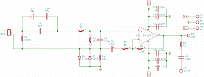
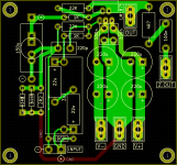
Hi AndrewT, could you have a look at my LM1875 schematic and PCB layout? I searched everything I found in this forum about LM1875 until now and final set for this. But I need to make sure it's ok.
My input cap will be ERO MKP1841 3u3 + 2 x Tantalum 150D 2u2, this combo sound best on my other amp so I still want to use it again.
My feedback cap will be Tantalum 150D 150u.
Other parts will be Pana FC + Dale CMF55.
Thanks!
My input cap will be ERO MKP1841 3u3 + 2 x Tantalum 150D 2u2, this combo sound best on my other amp so I still want to use it again.
My feedback cap will be Tantalum 150D 150u.
Other parts will be Pana FC + Dale CMF55.
Thanks!
Attachments
Last edited:
Unstable amplifiers have a sour tone and extra heat (fingernail size thermal interface of LM1875 won't forgive that). Therefore we should add the output filter parts as AndrewT indicated, so that we don't have a hot amp with a sour tone.
I would really appreciate it if everyone would go ahead and add the Thiele-Small output filter.
After adding the stability helpers, then the finish-up job of adjusting the gain suitably, is much easier and with a more productive outcome.
If snare drum is PFFT!!! and the audio is boring, the gain is too high.
If female singers are terribly angry and the amp is too hot, the gain is too low.
That's grossly approximate, but it is useful!
A finish-up job of setting the gain usefully for your amplifier in your application, is mandatory. It is not to be a pre-determined figure; but, it is to be whatever the amplifier needs to work best. There is a functional range in-between 20x~42x, and hopefully not set at either extreme. The figure may vary by need, especially of layout and voltage used.
- Home
- Amplifiers
- Chip Amps
- Beginner's Gainclone, HiFi LM1875, The Amplifier Board