Thanks, all. I am sorry I didn't try adding a bit more solder, as that makes sense--I was left with a small amount in the hole I couldn't wick out. Regardless, got a new set of micro drill bits (mine walked) and drilled it out. And finished it up. And plugged it in to the power supply...
On the positive side, no fire, no smoke. The red led's went on. I wasn't sure what to do, so I tested the voltage as recommended on the pcb near the pot. I put the red lead on the place near the pot, black on the ground in. I got an initial reading of around 5v, but it was not stable, it fluctuated across a large spectrum, steadily dropping well below zero, than higher. The led's would periodically go on for a bit, then off for a while. This seems bad. Can anyone offer suggestions? Not sure what to do.
Thanks!
Hate to ask, but can you explain how to short the inputs, keep the outputs open? And, should I put one lead on the test pad and one on ground? Thanks.Short the inputs. Keep the outputs open.
Put the meter (DC volts) on the test pad and adjust it (as best you can) to zero.
If that point calms down, then probe around to the other points on the boards and record your voltages.
Use this schematic -

Keeping the outputs open is easy - don't connect them to anything.
Shorting the inputs is also easy, take a clip lead and connect the input hot to the ground at the rca. Or take some old junky interconnects, cut most of the wire off, leaving 2 inch or so, strip and connect the wires together so the rca plug connects the hot to ground.
Yes, black on GND (at the PSU entry is fine.) probe with the red.
Ok, it is now interesting. Sorry to use this board for troubleshooting, but...
Hooked it up again. Wired as recommended above, started checking voltages. To start wit what I know, I checked past r3 and r4, got just below 24v as expected, did same with r31 and r33, got -24v on one, -31 on the other. This had happened earlier, but I thought I had fixed it when I cleaned up the solder. So I redid the solder around the voltage regulator, hooked it up again. Smoke! Resistors 30 and 32 on both boards smoked and died. I checked the voltage at the jack and it was +-34 as expected. I will replace the resistors, but don't want to just burn up another four. Any ideas?
Hooked it up again. Wired as recommended above, started checking voltages. To start wit what I know, I checked past r3 and r4, got just below 24v as expected, did same with r31 and r33, got -24v on one, -31 on the other. This had happened earlier, but I thought I had fixed it when I cleaned up the solder. So I redid the solder around the voltage regulator, hooked it up again. Smoke! Resistors 30 and 32 on both boards smoked and died. I checked the voltage at the jack and it was +-34 as expected. I will replace the resistors, but don't want to just burn up another four. Any ideas?
Time to build the light bulb tester, I suppose...or a bit late.
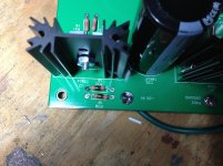
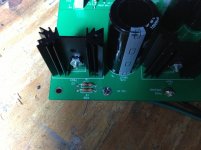
Here are the pics, not sure what you are looking for. Both boards were plugged in, both sets of resistors fried before the negative voltage regulator fried. No good reason for having both plugged in...
For what itis worth, my guess is that in"fixing" the solder for the regulator I created a short, which caused a surge and fried the resistors. In which case I would need to find out if I killed the regulator/s.
Attachments
Last edited:
") I burned mine a lot better than that.
I burned mine a lot better than that.Actually, back to help. No luck with desoldering braid, all suggestions appreciated.
Get a toothpick (round, in cross section). Moisten it (yep, saliva will work, in a pinch). Heat the pad for the clogged hole on the PCB. When the solder starts to flow, remove the heat and insert the toothpick (rotating it as you insert it). The solder will not stick to the moistened toothpick. Remove the toothpick, and you should have a clean round hole once again.
P.S. The U.S. Surgeon General has asked me to advise you'all to DISCARD the toothpick after you use it for this purpose..... Something about lead, getting into your body....!!

How do R31 and R33 look? Any discoloration? If any, the problem lies to the "audio side" of the schematic.
If only R30 and R32 were toasted, that suggests:
(1) the power supply is working (and you measured the negative voltage rail of the PSU disconnected from the amp boards, and confirmed that, true?)
(2) the problem lies around C26 (polarity installed correctly?) or the regulator U2.
You said R30 and R32 on BOTH channels were toasted? That suggests a parts "installation" problem first (i.e., C26 or U2) pinouts, and more remotely a soldering problem (i.e, unusual to have the same soldering issue on two separate PCBs).
Since R30 and R32 are now toasted, remove them, and measure the resistance from the R30/R32/C26 junction (placing the other meter lead on ground). If it measures zero, or very low, Check c26 and U2 as starting points:
(1). You certain you installed a "negative rail" regulator--they are very similar/identical to positive rail regulators?
(2) Did you ISOLATE the regulator from heatsink and chassis ground, if needed?
Last edited:
I just looked at your pics on Post 29 again. R31 and R33 on the one board I can see look OK.
I'd put my money on your U2 mounting. It might have to be electrically isolated from the heatsink (if the heatsink is grounded). That would entail using a THIN isolating pad (mica), thermal grease, and probably a non-conducting screw (i.e., nylon). I haven't done any other research into the tech sheet for U2, but I suspect that's your culprit..... the regulator tab is grounded via the heatsink.
I'd put my money on your U2 mounting. It might have to be electrically isolated from the heatsink (if the heatsink is grounded). That would entail using a THIN isolating pad (mica), thermal grease, and probably a non-conducting screw (i.e., nylon). I haven't done any other research into the tech sheet for U2, but I suspect that's your culprit..... the regulator tab is grounded via the heatsink.
The heatsink mount holes don't attach to ground. (Or at least they didn't on my PCB...) So the tab should be isolated. EDIT - I used full-pack TO-220 regulators, so it wouldn't matter on mine if they did or didn't attach to ground...
However, do check it and make sure you have no continuity from tab and/or heatsink to ground.
Did you originally check the PSU section with no heatsinks attached to the regulators?
However, do check it and make sure you have no continuity from tab and/or heatsink to ground.
Did you originally check the PSU section with no heatsinks attached to the regulators?
Last edited:
Yeppers.... I just dug up (the Internet is your friend) a datasheet for a 7924 -24v regulator, in the TO-220 package. The heatsink tab is internally connected to Pin 2 of the regulator, which is the INPUT pin coming from your power supply. Unless your (1) regulator is electrically isolated from the heatsink OR (2) your heatsink is isolated from the PCB ground, you have a DIRECT power supply-to-ground SHORT. I'm not familiar with your PCB, so I'd recommend you mount ALL FOUR regulators to their respective heatsinks using mica pads, thermal grease, and nylon hardware.
Once done, that should get you to your next level of testing. Good luck.
Once done, that should get you to your next level of testing. Good luck.
CanAm - ROTFLMAO!
JHS - I have some parts for you if you blew anything up... In the time being, can you tell us how many ohms you have from the screws holding the regulators to the heatsink to the ground pad? And can you take a photo of the bottom of the PCB where the regulators mount?
JHS - I have some parts for you if you blew anything up... In the time being, can you tell us how many ohms you have from the screws holding the regulators to the heatsink to the ground pad? And can you take a photo of the bottom of the PCB where the regulators mount?
Last edited:
- Home
- Amplifiers
- Pass Labs
- Beginner's Build Guide: Pearl II