Thanks for this and your website--excellent.
I too have come back and forth to this site. Made my first interconnects and speaker wires and now just want to keep building something.
I hope you give it a shot and describe your efforts. I am sure I would learn something from it!
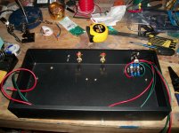
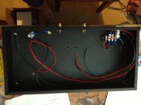
A few more shots, largely wrapping up the work on the case. One note: the hardest thing to solder I have found so far is the male xlr plugs. So what did I do? Reversed the wires, so positive went to negative and visa versa. My first thought was to just correct for it by changing the wiring in the pearl ii box, but in the end decided to fix it. Am I missing something, or are male xlr jacks a hassle to solder? Annoying. But moving along!
Attachments
Starting on the pcb's. A few thoughts:
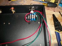
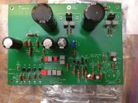
Below is a picture (ignore little transistor on the left, forgot to take picture before I put it in) of the voltage resistor and surrounding pieces. As recommended by 6L6, put those in first so I could make sure that I was getting the requisite 24 v out of this section (tested by temporarily hooking up the power supply to the board, putting tests on the output of R3 and ground input, similar with the DC- section). Got 23.7-23.8, so am starting to put in rest of components. This is done to avoid frying many of the transistors, I believe, if you have a problem with the power supply.
Soldering transistors is a pain. I find it difficult to get the transistor leads hot enough to melt the solder, particularly the middle lead. Every one is an adventure.
Transistors are "directional"--they have a correct orientation. I put in a few before this particular lightbulb went on, and then spent a fair bit of time trying to figure out if I had done it correctly. At some point I realized the pcb outline matches the transistor (a flat "back" and rounded "front"), to which all I can say is "duh". I had done it right, thankfully. Please make sure you do this properly.
For all my efforts with the BOM, I made several misorders. I forgot to order heatsinks for the voltage regulator, and ordered too few .1 uf capacitors and 3300uf capacitors. Mouser and USPS are doing well off of my errors. Don't just double check your order, triple check it.
Attachments
I don't know if you already did, but it's also handy to order some different values for a few components:
R14 lets you alter the gain, you could order something in the 500-750R range to get more gain. I needed different values for each channel to compensate for slightly different gain between both channels (0.5dB, compensated with 820R in one and 768R in the other)
R20 to experiment with cartridge loading. Some MC's are happy with 10R, some with 470R or something like that.
I needed a different value for R10 (8k2) to get Vc > Vb > Ve around Q3. But this might not be the case if you got your FET's from Pass. I had FETs with higher Idss, they require different values for R21-24 (20R in my case) and possibly R10.
If you want less subsonic rolloff, you can increase the value of C12 (I used .15).
I have also got some different values for C22, but most MC's don't really mind about capacitance.
Having spare ZTX450's and ZVP3310's is also wise, as many have had some fail (I did too with one ZVP3310. Don't know why. It might have been a bad one, or maybe I heated it too much while soldering...)
One note: the hardest thing to solder I have found so far is the male xlr plugs. So what did I do? Reversed the wires, so positive went to negative and visa versa. My first thought was to just correct for it by changing the wiring in the pearl ii box, but in the end decided to fix it. Am I missing something, or are male xlr jacks a hassle to solder?
It helps to have a "third hand" tool with XLRs.
For all my efforts with the BOM, I made several misorders. I forgot to order heatsinks for the voltage regulator, and ordered too few .1 uf capacitors and 3300uf capacitors. Mouser and USPS are doing well off of my errors. Don't just double check your order, triple check it.
Been there done that for sure. I think the published BOM might be off.
Oops, wrong format: trying again.
Quick note--I can't seem to edit the post with the BOM, but there is at least two mistakes: you need 22 of the .1 uf capacitors, not 14, and you need heat sinks for the two voltage regulators.
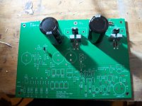
You started soldering with bigger electrolytic caps first?
IMO, you should start mounting smallest parts first - resistors, film caps, diodes/LED, electrolytic caps. Smallest means parts with smaller height from PCB plane and footprint when mounted. Then move to next bigger resistances and Caps. In the end, semiconductors with >=3 legs.
IMO, you should start mounting smallest parts first - resistors, film caps, diodes/LED, electrolytic caps. Smallest means parts with smaller height from PCB plane and footprint when mounted. Then move to next bigger resistances and Caps. In the end, semiconductors with >=3 legs.
You started soldering with bigger electrolytic caps first?
IMO, you should start mounting smallest parts first - resistors, film caps, diodes/LED, electrolytic caps. Smallest means parts with smaller height from PCB plane and footprint when mounted. Then move to next bigger resistances and Caps. In the end, semiconductors with >=3 legs.
Thanks, this makes sense. I put the big stuff in first to check to make sure I was getting 24V into the main section of the board, which was a good idea--I finally got the extra capacitors to put in the - channel of the second board, and lo and behold, 33V. I had soldered a connection poorly. Repaired, and now have 24 V. In general I will do it the way you suggest, if for nothing else ease of work. It unbalances the board having the big stuff in, which makes it a bit harder to solder.
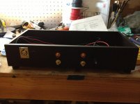
Quick update. Following a suggestion in the "Mistakes you learned from" thread (http://www.diyaudio.com/forums/pass-labs/233964-mistakes-you-learnt-might-helpful-beginners.html, I couldn't recommend enough), i tried to straighten the rca inputs on the pearl case by tightening two nuts around a bolt threaded through the hole, which lead to a definite improvement. I put feet on the cases, and finished the interior of the pearl case. Finally, I put in most of the components to the pearl pcb's. I realized that I had (by following a piece of someone else's BOM without really asking why) ordered variable capacitors (3pf-11pf) in place of the 5pf capacitor called for in the schematic. It would not fit into the place on the pcb, as it was too small and the connections were a bit too wide. Thinking that it was all that was between me and getting the pcb finished, I soldered some jumpers to it. I wasn't convinced that this was a good idea, so didn't put it in the pcb. Ultimately, I realized I had ordered the wrong size heat sink (EA-T220-38E, I believe, is the right one, I had ordered FA-...) so I had to place another (sigh) order to Mouser anyway. I added a few 5pf capacitors.
Below are a few pictures. I am trying a new camera (well, phone). Borrowing from WC, I see this as getting close to the end of the beginning--by this weekend I should have it all together, or at least the pcb's running so I can check if they work. We will see if it is the end of the end. As always, if you notice anything stupid please tell me.
Also, does anyone have any suggestions re: the installation of the heat sinks? Should I solder them to the board or just screw them to the voltage regulator? Thanks.
Attachments
you haven't forgotten C24 I hope? (or were those the ones you had too few of?) Also installing C7 might get you into trouble by causing oscillation.
I was waiting until I put in the 5pf capacitor to put in C24, so good there. Do some people leave off C7? I did not know that. At least I will have someplace to look if I have that problem.
Yes, C7 caused trouble in some people's builds. I never put it in.
I had trouble with oscilliation and pulling C7 solved. In the main Pearl 2 forum thread, and after the Pearl 2 article was published, Wayne recommends leaving out and said he had oscillation in a subsequent build.
jhsjhs99 - Have you fired it up yet?
No, should finish it sometime this weekend probably. Want to get a fire extinguisher handy (joking, joking).
Help!
It had to happen-on the last (last!) solder, I get a bit cute trying to neaten up the ground out wire on one of the pcb's and managed to fill the hole on the pcb with solder. I haven't been able to get it out. I cant get the wire back in. Any suggestions?
Thanks!
Edit:
Found this, should have checked first: http://www.robotroom.com/Desoldering-Holes-1.html
Will try with the braid, as it is all I have.
Last edited:
Actually, back to help. No luck with desoldering braid, all suggestions appreciated.
Heat it and bang the board against a table?
- Home
- Amplifiers
- Pass Labs
- Beginner's Build Guide: Pearl II