
As I have a small good quality torque wrench I would like to find out if there is a recommended torque load for securing such devices to heatsinks? Irish logic tells me that if they are all mounted at the same loading, then more equal transfer should occur. But what is the ideal loading?
Papa mentioned 3.5 inch-pounds in the SoZ article:
https://www.passdiy.com/project/amplifiers/son-of-zen
so that's probably a good value to start.
Hello everybody
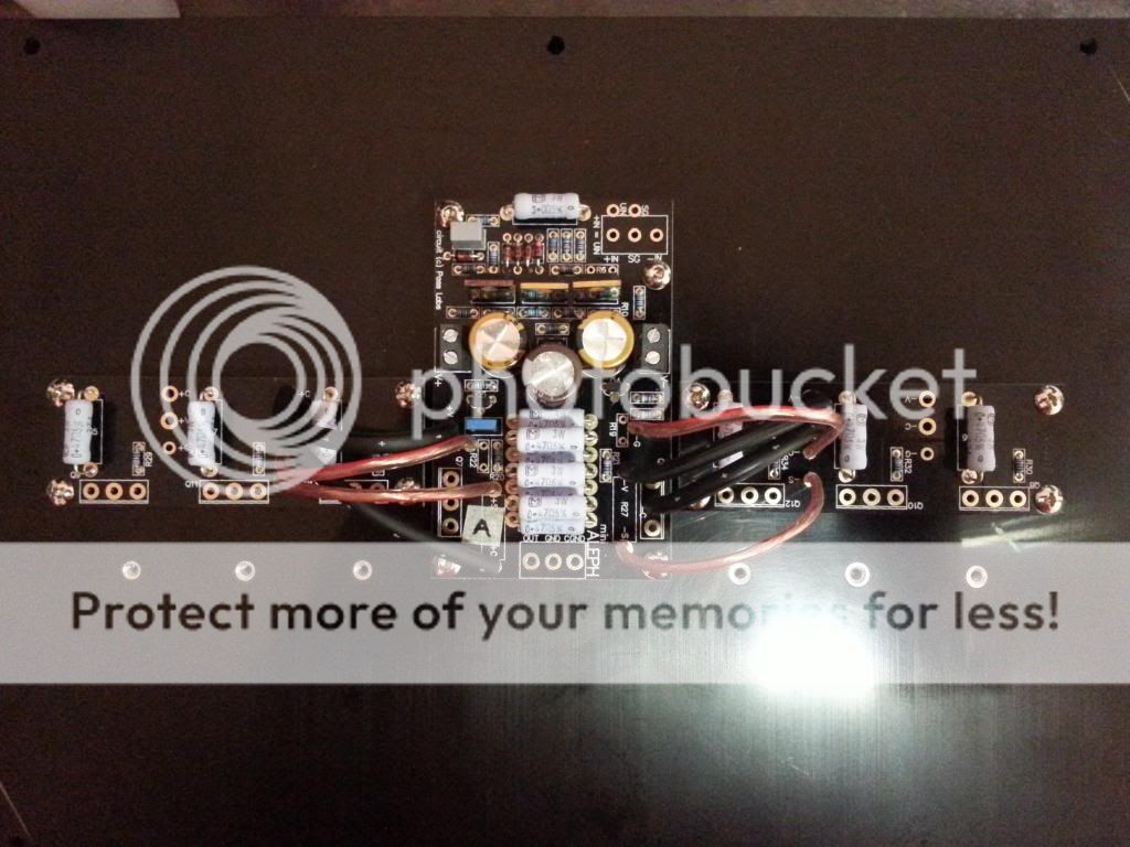
So today, I've done the machining on one heatsink (drilling and tapping M3 and M4 holes on the sink edges in order to fix the chassis plates), I ain't done any photos cause my wife has requisitioned my phone, I will take pictures for the second one.
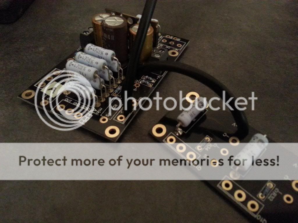
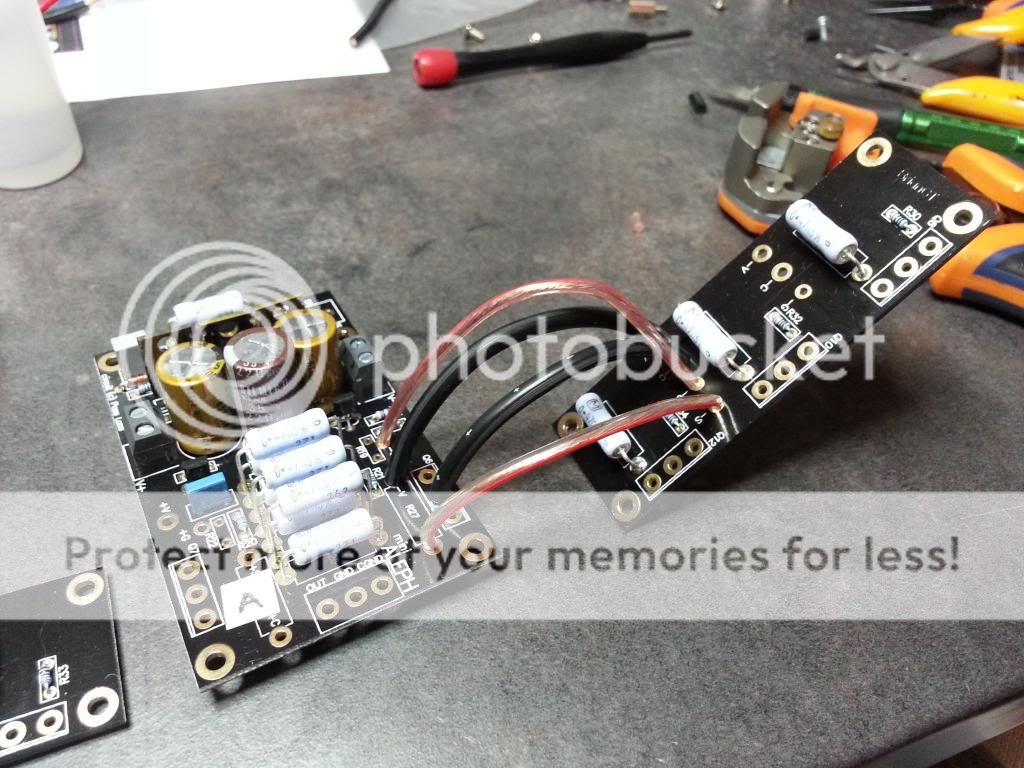
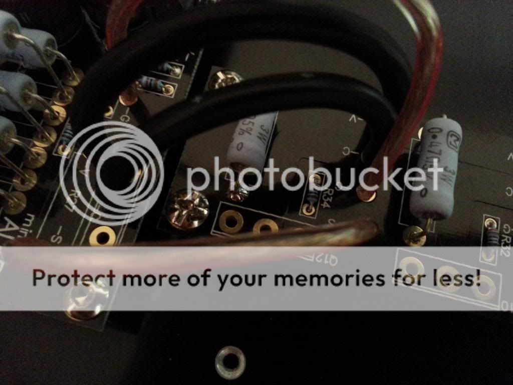
I also done the wiring between amp and header boards
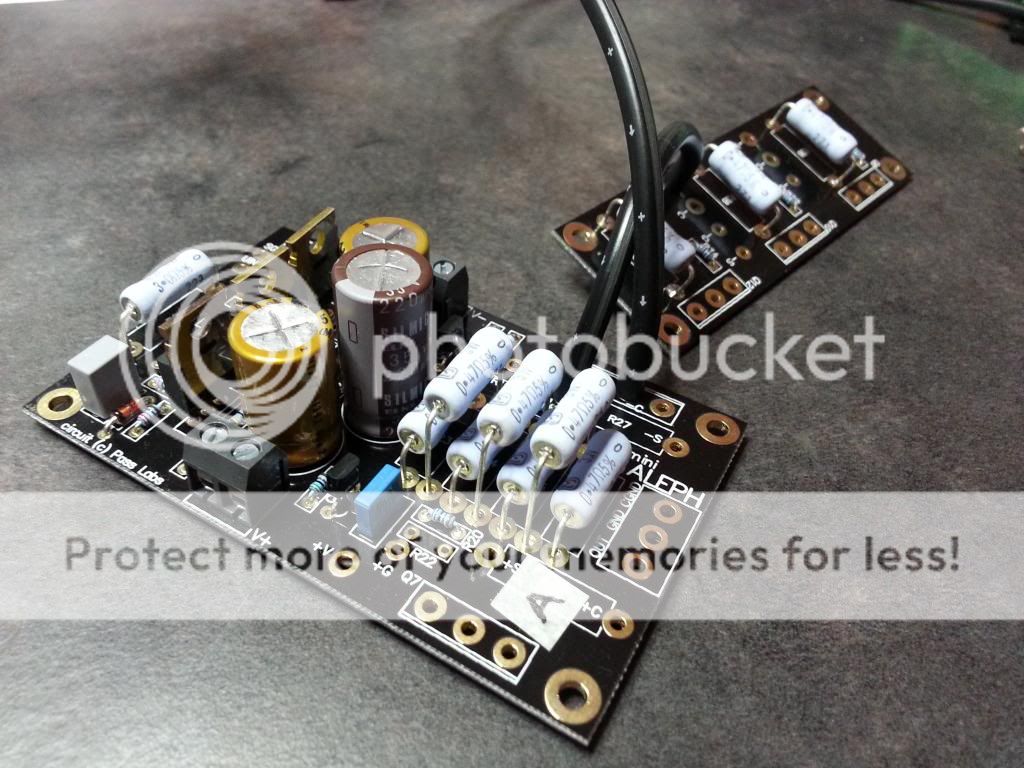
I used HP OCC wire (2,5mm for V and C, 1.5mm for G and S)
So today, I've done the machining on one heatsink (drilling and tapping M3 and M4 holes on the sink edges in order to fix the chassis plates), I ain't done any photos cause my wife has requisitioned my phone, I will take pictures for the second one.
I also done the wiring between amp and header boards

I used HP OCC wire (2,5mm for V and C, 1.5mm for G and S)


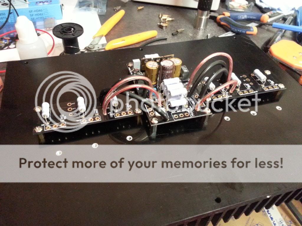
So yesterday I've received my laser etched aluminium plates......I'm thrilled  they are top notch, and It seems like I made good measurements as everything screws in place without a hiccup!
I had to do a lot of sanding on them as they were made from raw aluminum/magnesium plates, I'll post pictures showing the before/after sanding job.
However I have some questions for what is coming next, say "Testing the whole damn thing"
- I have to decide If I solder the signal input and output wire directly on the amp boards or if I use terminal posts. Is there really an impact on sound quality if I use terminal posts?
-I have to decide about my grounding scheme, I plan on using two separate ground point on the chassis:
*One only for main ground (taken directly from IEC ground connection)
*One for all the boards DC ground, located near the first one, maybe 2cm away (I'll link PSU output DC ground, amp boards DC GRD IN, Speaker protection DC GRD IN)
*I plan on linking RCA/XLR GRDs directly to the amp board and the HP posts GRDs directly to the speaker protection boards
Does it seems good to you?
-I want to be able to switch between balanced (XLR) and unbalanced (RCA) input, so I wanted to know how to wire the two input through a switch to do that.
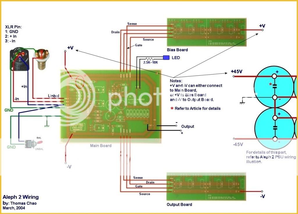
Is this method correct?
I'll draw a schematic of my entire project later today, It will probably be clearer this way.
they are top notch, and It seems like I made good measurements as everything screws in place without a hiccup! I had to do a lot of sanding on them as they were made from raw aluminum/magnesium plates, I'll post pictures showing the before/after sanding job.
However I have some questions for what is coming next, say "Testing the whole damn thing"
- I have to decide If I solder the signal input and output wire directly on the amp boards or if I use terminal posts. Is there really an impact on sound quality if I use terminal posts?
-I have to decide about my grounding scheme, I plan on using two separate ground point on the chassis:
*One only for main ground (taken directly from IEC ground connection)
*One for all the boards DC ground, located near the first one, maybe 2cm away (I'll link PSU output DC ground, amp boards DC GRD IN, Speaker protection DC GRD IN)
*I plan on linking RCA/XLR GRDs directly to the amp board and the HP posts GRDs directly to the speaker protection boards
Does it seems good to you?
-I want to be able to switch between balanced (XLR) and unbalanced (RCA) input, so I wanted to know how to wire the two input through a switch to do that.

Is this method correct?
I'll draw a schematic of my entire project later today, It will probably be clearer this way.
-IEC safety gnd to chassis
-both RCA and XLR isolated from chassis ; signal to pcb (all 3 wires)
-cap bank gnd to pcb , where it became main audio gnd point
-both pos and neg to speaker post from pcb
-CL60 or similar NTC (up to 20R) connecting main audio gnd ( you can take it also from cap bank gnd) to chassis
-take care about cap bank wiring arrangement

That will probably be OK, are you going dual PSU? Sorry don't remember. If so, since you're using the board as the channel star point, go from there to the NTC and make that your star of stars. Single PSU that's correct as depicted - the PSU Ground becomes the star of stars.
Hard to tell, but if it's grounding the negative input when you go RCA then you're good. And since you're taking the RCA ground to the XLR, why not take the RCA hot to the positive terminal there, too? (avoid a potential ground loop) Twist all signal leads to their returns.

Hello everybody!
Well I think this thread will be helpfull for other as........ it does not work
This is what I've done:
I build the enclosure and made the necessary connections:
I tested the PSU+Fan controller+ speaker protection relays with no trouble at all (the bulb light then dim quickly to no light at all), the fan starts, the relays clicks, the psu outputs 32V dc on each rails (V- / V+).
The problem occurs as I connect my amp board. The light bulb light then quickly lights a little more and stay lit, the fan doesn't starts, the relays doesn't click, the psu starts (blue led lights) but only outputs 6.5V DC on both rails.
.... somethings odd
Nothing smoked or smelled burnt, so I guess the bulb tester done it's job of protecting the components.
I checked that the fets are electrically isolated from the sinks (no continuity with the tester between fet legs and sink)
I don't really know where to begin.
I'll make a drawing to show you the overall connections I made (Including transformers and fuse rig)
The bulb will stay lit at some level because the amp draws significant current in operation. Are you still using a 40W bulb? Try 100 or 150. Even then there will be some glow. If the rails are the correct polarity and a bit higher with the higher wattage bulb, go ahead and start up without a bulb.
Edit: One channel at a time, right?
Edit: One channel at a time, right?
Last edited:
Disconnect the amplifier circuits and test only the PSU. Measure voltages, polarity, etc...
Connect fan, check that it's functional.
If that tests good connect one amp channel, test, adjust.
Repeat with other side.
When amplifier circuit is operational, add the protection circuit.
Wiring everytihng, hoping for the best, and turning it all on is a recipe to destroy something...
Connect fan, check that it's functional.
If that tests good connect one amp channel, test, adjust.
Repeat with other side.
When amplifier circuit is operational, add the protection circuit.
Wiring everytihng, hoping for the best, and turning it all on is a recipe to destroy something...
Well, I already done the test with only PSU + speaker protection relays and fan controler and all went fine (PSU outputing 32V DC on both rails, fan working and relays clicking)
As for the test with amp board, I've only tested with one channel, as the other one is not even built yet
As for the test with amp board, I've only tested with one channel, as the other one is not even built yet
- Status
- This old topic is closed. If you want to reopen this topic, contact a moderator using the "Report Post" button.
- Home
- Amplifiers
- Pass Labs
- Beginner to build an Aleph30 needs some help