Thanks.
My sim wasn't working as it should, and yours seems to work better.
As this is the time to play, I decided to see what happened if I added a DC Servo to the simulation, and the results seem quite promising.
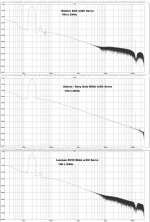
Run the included file and look at THD, both at 1K and 20K.
If the simulation is right, the results are amazing.
My sim wasn't working as it should, and yours seems to work better.
As this is the time to play, I decided to see what happened if I added a DC Servo to the simulation, and the results seem quite promising.
Run the included file and look at THD, both at 1K and 20K.
If the simulation is right, the results are amazing.
Attachments
Hi carlmart.
That looks very good.
With the servo you can omit the resistors PP and PN (= 0 ohms).
Why extra power supply for the servo? I ran the simulation with same supply for all, it makes no difference.
My PCBs are already done. But one could perhaps put a small piggyback board with the servo on them.
That looks very good.
With the servo you can omit the resistors PP and PN (= 0 ohms).
Why extra power supply for the servo? I ran the simulation with same supply for all, it makes no difference.
My PCBs are already done. But one could perhaps put a small piggyback board with the servo on them.
Hi carlmart.
With the servo you can omit the resistors PP and PN (= 0 ohms).
Why extra power supply for the servo? I ran the simulation with same supply for all, it makes no difference.
My PCBs are already done. But one could perhaps put a small piggyback board with the servo on them.
Of course you're right about not using a separate supply for the servo.
But I was thinking of using a Jung style supply for the main power and a separate one for the servo.
Yes, it's very easy to assemble a prototype piggy-back for testing the servo with actual audio, and see what changes. Eliminating the input and feedback caps could bring big improvements. But this have to be listened to.
When you put a DC servo around a RIAA amplifier, its poles start shifting. That is, you may have to tweak the values of the RIAA correction circuit a bit to get accurate RIAA correction. (Maybe this comment doesn't apply to the circuit you are discussing, I can't read asc files at the moment so I have no idea what the precise circuit is.)
When you put a DC servo around a RIAA amplifier, its poles start shifting. That is, you may have to tweak the values of the RIAA correction circuit a bit to get accurate RIAA correction. (Maybe this comment doesn't apply to the circuit you are discussing, I can't read asc files at the moment so I have no idea what the precise circuit is.)
It's to be expected that a DC servo might shift things a bit when it's applied on a filter. Though I wonder if there's a way to simulate that shift.
In the case of the opamp pre sim, the servo was applied by the designer, so it should be correct.
I'm not sure I can show those designs here, because of copyright reasons, and also because it would mean taking the focus off the SLN project.
But here are the three asc sims that can be run on LTSpice.
The SLN sim, set for 30Hz does show a great increase on the THD figure, even if that doesn't show to be so serious on the curve, which still looks quite good.
Attachments
And now the whole as SMD design, where possible, would be fine!
As long as it can hand assembled, it would be fine.
I'm not sure about the RIAA capacitor quality you can get in SMD, compared to the recommended polystyrenes.
NP0 a.k.a. C0G has a bit more more dielectric absorption than polystyrene, but linearity, stability and quality factor are quite good. The temperature stability is actually better than polystyrene. Mouser has some NP0 SMD capacitors with 1 % tolerance. For critical resistors, especially when 1/f noise matters, use thin film rather than thick film types.
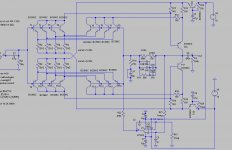
screen copy for those who can't use .asc-files: (modified SLN/Supra1)
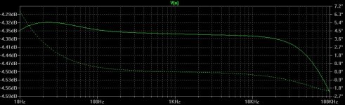
Circuit & simulated frequency response with reverse-RIAA input signal.
OK, the servo is slow enough not to shift poles significantly. Great!

As long as it can hand assembled, it would be fine.
I'm not sure about the RIAA capacitor quality you can get in SMD, compared to the recommended polystyrenes.
Hi carlmart,
that why i wrote, where it is possible, but the semiconductorrs and resistors (1206 or minimelf= same padsize).
It would be great to find complementary low-noise transistors cased together in groups of four per case to assemble the whole preamp. And then compare it with the through-hole discrete assembly.
Say four NPN and four PNP.
Same case with SMD resistors. COGs can be found in through hole versions too, though I'm not sure of the precision %.
Say four NPN and four PNP.
Same case with SMD resistors. COGs can be found in through hole versions too, though I'm not sure of the precision %.
If the values are standard, I think it's worth using polypropylenes. Wima are widely available, and come in 1% and 2.5% on some values.
Some higher quality DACs or preamps that are all SMD use polypropylenes.
I was warned that film capacitor SMDs can change value when soldering.
Some higher quality DACs or preamps that are all SMD use polypropylenes.
I was warned that film capacitor SMDs can change value when soldering.
- Status
- This old topic is closed. If you want to reopen this topic, contact a moderator using the "Report Post" button.
- Home
- Source & Line
- Analogue Source
- BC550 BC560 Very low noise RIAA