the miller capacitance will limit the HF < 50khz.
I put a filter on the head amp on mine at 30khz. The head amp has a flat gain of 15 and the RIAA op amp is set up to use signals of 35mV at 1 khz.
I have a Jfet there now but a single 2N5410 low noise transistor delivers 84db s/n.
I put a filter on the head amp on mine at 30khz. The head amp has a flat gain of 15 and the RIAA op amp is set up to use signals of 35mV at 1 khz.
I have a Jfet there now but a single 2N5410 low noise transistor delivers 84db s/n.
have you tried to adjust some value of the components in the riaa section?
the sound of the SLN is very controlled in the bass section but this was well known.
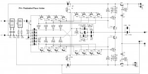
what about resistors in orange oval in PSU section, is it correct value? what about in yellow oval? do you have some accurate schematic?
Attachments
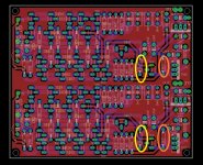
22k is rightwhat about resistors in orange oval in PSU section, is it correct value? what about in yellow oval? do you have some accurate schematic?
the miller capacitance will limit the HF < 50khz.
Miller capacitance also loads the cartridge, which my become an issue with those who are very susceptible to that, i.e. need low C, such as most AT's, but less of a problem for good old Shure's.
Best regards!
Is that 0.001ohms or 1000000ohms?........... 1m ohm resistor ..............
Interesting finding this thread.
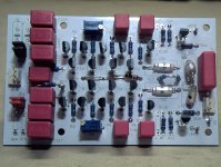
The original SLN Elektor preamp was the first RIAA preamp I assembled. I made the pcb myself following the original Elektor design. This was about 35 years ago, so some of you weren't even born yet!
The sound was very good, but what I could not control was a hum that apparently the supply was causing. The brain cancels the hum after some time, so I could listen and evaluate the sound quality anyway. But I ended up discarding it and later on extractin the parts for another project. That was a mistake.
But I think there're two parts I would suggest everyone to change: the regulators. Use at least 3X7 types instead of the 7X15 types. I remember substituting one 317 type on a single ended RIAA preamp, replacing a 7815, and the improvements were enormous.
If I remember well, the SLN highs were a bit over the top, but that also made some records to sound very much 3D, pinpointing jazz instruments, for instance. The RIAA caps were a dark green 10mm x 5mm I could never identify. They were 2% types. At the time I knew little of capacitor types. Certainly I would use polystyrene or polypropylene now.
Recently I thought of redesigning the pcb, routing the grounds in a different way. I wonder why all the secrecy involving the Supra 2. When I first saw the pcb I didn't know the ICs were LT1028s in parallel. I thought every IC held two transistors. That might be cool way to assemble the Supra.
I do have to build a good quality RIAA so I can capture all my LP collection. Recently I did that on a friend's setup, with a Luxman preamp and Thorens TD150. Converted the audio onto my laptop using a Behringer DAC.
The results were superb, particularly because I could process the audio with Audacity, removing surface noise and pops.
This time I would use a different DAC: a Tascam DR-70D. Higher bitrate and oversampling.
But all mus start with a good RIAA preamp.
Last edited:
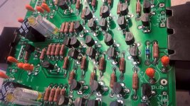
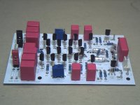
Good pictures. I have get such a diy version for sound enhancing. The most disadvantage of this approach is the too low idle current for each transistor - with considerably less than 0,5mA (10-13mA/each transistor would be perfect). Thus the sonic quality isn't really good. To find out the right calculation- and modification steps I ask the question therefore in an other thread to the same topic - unfortunately wrong filed.
check out therefore post 27 and 31 under
SLN Pre-Amp - Elektor Aug 1982
check out therefore post 27 and 31 under
SLN Pre-Amp - Elektor Aug 1982
Good pictures. I have get such a diy version for sound enhancing. The most disadvantage of this approach is the too low idle current for each transistor - with considerably less than 0,5mA (10-13mA/each transistor would be perfect). Thus the sonic quality isn't really good. To find out the right calculation- and modification steps I ask the question therefore in an other thread to the same topic - unfortunately wrong filed.
check out therefore post 27 and 31 under
SLN Pre-Amp - Elektor Aug 1982
The low bias current of the input stages is precisely why the equivalent input current noise is OK. That is, the currents are already above the optimum for moving-magnet cartridges, but it is not too bad.
With 10 mA per transistor, so 20 mA per pair, the base shot noise of each of the eight input devices would be sqrt(2*1.6022E-19 C*10 mA/600) ~= 2.31 pA/sqrt(Hz). For all eight together that would be 6.54 pA/sqrt(Hz), which would make the Supra's current noise as bad as that of the Supra 2.0 (which is by far the worst moving-magnet amplifier I've ever seen).
You can calculate the impact on A- and RIAA-weighted noise by multiplying it by the cartridge impedance at 3852 Hz and multiplying it by the square root of the noise bandwidth, which is 3219 Hz. With a cartridge inductance of around 500 mH, it boils down to 4.488 uV(A). With a sensitivity of 5 mV, that's around -60.94 dB(A), similar to the surface noise of a new record played dry.
I can not imagine that this does a matter during record playback, because the record surface noise has SNR values arround 50-55 db.The low bias current of the input stages is precisely why the equivalent input current noise is OK. That is, the currents are already above the optimum for moving-magnet cartridges, but it is not too bad.
With 10 mA per transistor, so 20 mA per pair, the base shot noise of each of the eight input devices would be sqrt(2*1.6022E-19 C*10 mA/600) ~= 2.31 pA/sqrt(Hz). For all eight together that would be 6.54 pA/sqrt(Hz), which would make the Supra's current noise as bad as that of the Supra 2.0 (which is by far the worst moving-magnet amplifier I've ever seen).
You can calculate the impact on A- and RIAA-weighted noise by multiplying it by the cartridge impedance at 3852 Hz and multiplying it by the square root of the noise bandwidth, which is 3219 Hz. With a cartridge inductance of around 500 mH, it boils down to 4.488 uV(A). With a sensitivity of 5 mV, that's around -60.94 dB(A), similar to the surface noise of a new record played dry.
Is this the above mentioned SUPRA 2.0 ?
https:// ciit d/labs/supra-20-high-end-preamp-for-record-player-150616-i
Can you upload the associated circuit diagram ?
50 dB to 55 dB is either not A-weighted or quite bad; in this thread, https://www.diyaudio.com/forums/analogue-source/313160-mm-mc-phono-stage-4.html#post5223605 , measured levels were around -60 dB(A) with respect to 5 cm/s at 1 kHz on a new record played dry. I don't know by how much the surface noise can be reduced by playing records wet. If you allow 1 dB of reduction of a 60 dB(A) signal-to-noise ratio, the amplifier's noise has to be below -66 dB(A).
In any case, even if you were right, people on forums like this usually worry about things that are not likely to be audible under any circumstance, so noise that's only audible when the record is standing still is worse than most of what diyaudio is all about.
The Supra 2.0 I wrote about is the Elektor Supra 2.0, a moving-magnet amplifier with four paralleled LT1028's per channel to get super high current noise: Supra 2.0 | Elektor Magazine
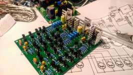
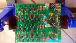
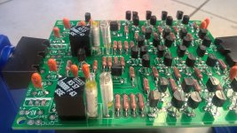
I made a PCB layout and made some minor changes to the circuit.
I did not have the exact values for some Rs and Cs, so I used some flying soldered parts for the first test.
It works, sounds OK. One board is for one channel.
I did not have the exact values for some Rs and Cs, so I used some flying soldered parts for the first test.
It works, sounds OK. One board is for one channel.
Attachments
Very nice! Congratulations!
What did you think about the sound quality?
What regulation are you using for it?
Some questions:
1) Why did you add C1 (4u7uF) that is not on the original project?
2) Why didn't you separate, at least on the schematic, the audio grounds from the supply grounds?
3) Your pcb design is single sided or double sided?
4) How do you do to see the THD on the LTSpice simulation?
Thank you carlmart ")
Sound:
I just tested it briefly, (with some classic music -Mozart, Mussorgsky-, and some Rock, Funk), and it sounds okay to me.
I can not confirm the exaggerated heights described by others.
I'm currently using an ortofon OM-pickup
Regulation:
You mean power supply? Currently it's a simple circuit with LM 317/337 regulators.
#1.)The offset DC voltage at the output (before C8) is also dependent on R1. I want the offset to be as small as possible and constant. If you connect the pickup and/or additional resistors to adjust to the pickup, the offset changes. The C1 prevents this. The offset then would change in the range from approx. + - 500 µV to approx. + -10 mV. But one can perhaps tolerate this, because there is also the output capacitor C8.
The output offset can be matched with the trimpots.
#2.) ???
That is probably due to my handling of the layout program. There is only one "ground" there.
But don't worry, there is no hum or anything like that.
#3.) Both.
The top layer is just ground/shield
#4.) e.g.:
- replace the semicolon at the "tran..."-line with a point
- replace the point at the "ac oct..."-line with a semicolon
- then run the simulation.
- view error log
I just realize that the parts indices are different between the circuit pic and the .asc-file. Sorry.
Back at the time of the first publication of the SLN, I built it using the same pcb they published, and I had hum.
Unfortunately I was impatient and inexperienced, because in spite of the hum the preamp sounded very realistic.
No cap at the input, and nothing wrong because of that.
The 7X15 regulators should have been replaced with at least 317/337. Nowadays I would use a pair of Jung superregulators.
What I think happens when you connect the pickup is surface noise and motor noise, particularly on belt driven record players. What should take care of the offset is a DC servo, also eliminating the output cap.
Can you correct the parameters on the asc file in order to see THD and upload it here?
- Status
- This old topic is closed. If you want to reopen this topic, contact a moderator using the "Report Post" button.
- Home
- Source & Line
- Analogue Source
- BC550 BC560 Very low noise RIAA