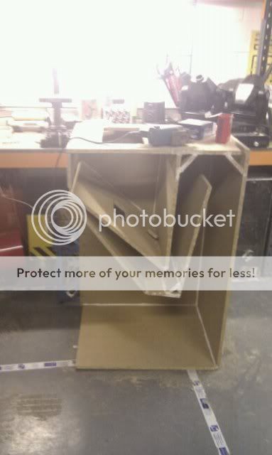
Alright folks! Im new to this forum so bare with me. This week i have build a VERY rough version of a Vitavox Thunderbolt, i will be building the mark 2 version this week, so i can improve on my mistakes!
I am mainly just after a bit of advice on cross overs really, i have purchased a 2way cross over with the intention of just using the bass output (i wanted to buy it on the day and that was the most suitable i could find). However my boss tells me i shouldn't need a x-over inside it as the box/driver will cut out the frequencies its self.
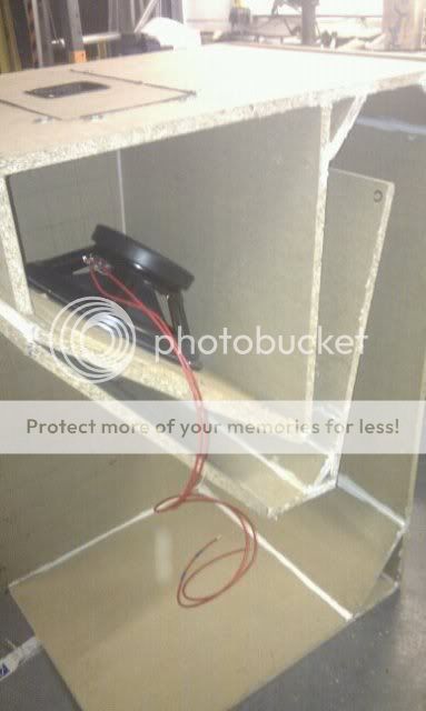
The build has been very budget, i have installed an Eminence Kappa 15 driver in the box. I will upload pictures soon, just putting them on my facebook now.
I am mainly just after a bit of advice on cross overs really, i have purchased a 2way cross over with the intention of just using the bass output (i wanted to buy it on the day and that was the most suitable i could find). However my boss tells me i shouldn't need a x-over inside it as the box/driver will cut out the frequencies its self.
The build has been very budget, i have installed an Eminence Kappa 15 driver in the box. I will upload pictures soon, just putting them on my facebook now.
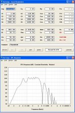
To answer your question requires a little reverse engineering of a 1975 horn. I did a 'VERY' rough guess at some of the hornresp parameters, and also guessed you are using the kappa 15LFA. (or is it the kappa 15a)
Regardless it looks like it is very well behaved up to the 500hz cutoff where it was crossed to a multicell compression driver. I would definitely put a crossover on it, as you'll get some stuff above 500hz that you really don't want. You'll also want to highpass this at 40hz.
Don't take the below 100hz too seriously, until there is some refinement to the hornresp parameters. (and actually have the correct driver info, if I guessed wrong)
This should be very interesting in your house... (guessing in house since you are not using plywood??? man that's gotta be heavy.) It's big, and for a 1975 design, I'm suitably impressed. Let's see pics when it's complete.
Attachments
Last edited:
Thanks for the reply (ive not been checking back all day, i promise). I think ill have a bash at making my own x-over for this box. It is actually made out of chipboard, cheap and cheerful, i am getting a price on MDF/Ply tomorrow and im going to make a decision on what to use for the next one.
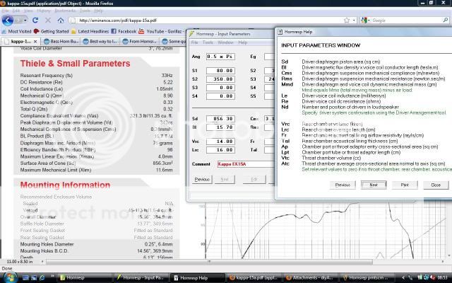
The box its self is very efficient (apparently i wouldnt know) How did you calculate all of that technical wizardy in the attached thumbnail might i ask? Is there such thing as a piece of software where you can enter the size/design of your box (cad style) and it will tell you how efficient/what frequencies you can expect from the box.
The big gap at the front is causing me issues at the moment, i will mitre a piece of wood to block it up tomorrow i think, but as for the rest of the box it is very tightly sealed") . Im in a speaker installer, not a joiner haha!
. Im in a speaker installer, not a joiner haha!
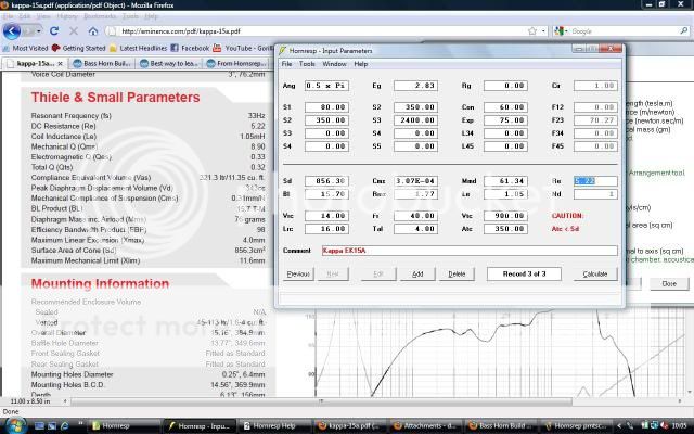
It is the Kappa 15A, i was going to go for the Delta 15 however it wasn't in stock and i wanted to get it running. For the next version im tempted to buy a more expensive driver however ive been told its pretty pointless due to the efficiency of the box, and any driver rated near or above 1000RMS the box needs strengthening more.
Thanks for the reply! Im after some criticism so i know where to improve, ive just finished an electrical apprenticeship but i work for an audio company, but still being at installer level i havn't got to learn much of the design side yet
The box its self is very efficient (apparently i wouldnt know) How did you calculate all of that technical wizardy in the attached thumbnail might i ask? Is there such thing as a piece of software where you can enter the size/design of your box (cad style) and it will tell you how efficient/what frequencies you can expect from the box.
The big gap at the front is causing me issues at the moment, i will mitre a piece of wood to block it up tomorrow i think, but as for the rest of the box it is very tightly sealed
. Im in a speaker installer, not a joiner haha!It is the Kappa 15A, i was going to go for the Delta 15 however it wasn't in stock and i wanted to get it running. For the next version im tempted to buy a more expensive driver however ive been told its pretty pointless due to the efficiency of the box, and any driver rated near or above 1000RMS the box needs strengthening more.
Thanks for the reply! Im after some criticism so i know where to improve, ive just finished an electrical apprenticeship but i work for an audio company, but still being at installer level i havn't got to learn much of the design side yet
Hornresp
HORNRESP.... It will model anything you want, and it's free.
It's awesome, and I take my hat off to David. Thanks for such a great piece of software.
Once you get the horn parameters set to accurately reflect what you are building, you can substitute one driver for another, and see exactly what to expect.
Keep in mind everything is in metric. (cm or cm2)
Search for some of the great hornresp tutorials, or even use the very helpful F1 help feature.
Right, just trying to get my head around Hornsrep, ive come to the RMS box on the lower half of the page, im trying to enter the details for my driver and i cant find the RMS figure
Would i be right in thinking the RMS is shown as the Qes on the website?
OR
is there anyway i can calculate the RMS from the figures given on the website
An externally hosted image should be here but it was not working when we last tested it.
Would i be right in thinking the RMS is shown as the Qes on the website?
OR
is there anyway i can calculate the RMS from the figures given on the website
is there anyway i can calculate the RMS from the figures given on the website
Just doubleclick on the RMS parameter in Hornresp.
Frode
3.07E-04 is another way of writing 3.07 * 10^-4 = 3.07 / 10^4 = 3.07 / 10000 = 0.000307m/n = 0.307mm/n.i got a reading of 3.07E-04, how does this match the websites stated figure of 0.31mm/n?!
That is a difference of ~1%, probably OK !
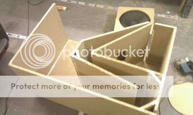
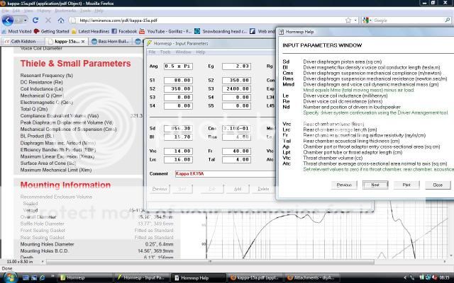
I thought I'd doctor up a hornresp input screen, to help make sense of things since the thunderbolt is an 'offset driver' front loaded horn. I did some guessing on lengths and areas that are 'not exactly' right, but close. It should be enough that you can fill in the actual lengths and areas and have a good model of this horn. (edit on image: vtc, 1000 = 1 liter, vrc 98 = 98 liters)
Once the model is right, you can change the input voltage, calculate spl, and always check the displacement, to find out when your driver runs out of gas and at what frequency.
Once the model is right, you can change the input voltage, calculate spl, and always check the displacement, to find out when your driver runs out of gas and at what frequency.
Attachments
Hi jbell,
Nice work on the Hornresp Input. There is one area you could refine: the Atc should be the area inside the mounting ring of the driver, and Ap1 should be set to equal S2, then Lpt becomes the thickness of the mounting board. Also, the flare rate should be set to Par. It should make little difference in the SPL output.
Regards,
Last edited:
Okay so your Hornsrep looks different mine, if you look at my screenshot
Where you have entered all of the different Flar lengths (Con) i have different boxes? Can you shed any light on this please?
Also am i right in which i think are the different CON measurements
Please forgive my caveman style illustration
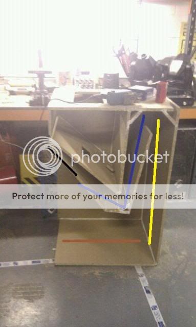
Black line = CON (1)
Blue line = CON (2)
Yellow line = CON (3)
Brown line = CON (4)
Where you have entered all of the different Flar lengths (Con) i have different boxes? Can you shed any light on this please?
Also am i right in which i think are the different CON measurements
Please forgive my caveman style illustration
Black line = CON (1)
Blue line = CON (2)
Yellow line = CON (3)
Brown line = CON (4)
- Status
- This old topic is closed. If you want to reopen this topic, contact a moderator using the "Report Post" button.
- Home
- Loudspeakers
- Subwoofers
- Bass Horn Build (The Thunderbolt)