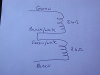
I made small test with multimeter
Primary:
Green/white green - NONE
Green/white black - 3.6Ohm
Black/white green - 3.6Ohm
Black/white black - NONE
Sec:
Red-Red - 150Ohm
Brown-Brown - 1.6Ohm
Yellow-Yellow - 1.6Ohm
I dont know about the secondaries but they might mistake with the primary colors ?!
"none" = zero ohms?
The above data is with all four primary wires not connected to anything? ie the black/white-green connection is not connected?
It appears that the color coding of the wires is incorrect..........
If you connect the Black/white to the green/white wires do you get 7.2 ohms across the green and black wires?
You just figured out your problem.....
There it is, the black/white and green white wires were reversed at the Factory.
Connecting 240V across the green/white and black wires would certainly blow the fuse, since you area only going across one primary; half the impedance pulls twice the current.
Meters are not very accurate at very low ohm readings, that's why you are seeing 6.8R instead of 7.2R.
....and it only took 63 posts to figure this out....
You need to wire like this:
Nice!
Attachments
Last edited:
Looks promising ....
Is it matter if I config it as the drawing you supplied or in any other configuration which finally gives 7.2Ohms (for instance green/white to POWER,black to black/white and green to POWER)
BTW: I would never catch that if I wont see the related post ....
Is it matter if I config it as the drawing you supplied or in any other configuration which finally gives 7.2Ohms (for instance green/white to POWER,black to black/white and green to POWER)
BTW: I would never catch that if I wont see the related post ....
Connect your mains wires, switch and fuse to the black and green wires, then CAREFULLY check the AC voltages on the secondaries. They will be a little high with the transformer not connected to the board. Clip leads on the red and red/black leads are HIGHLY RECOMMENDED.
Then connect the 6V and 5V filament wires to the board and install the tubes and verify that the filaments glow. Tape off the loose red and red/black wires.
Then finally connect the red and black/red leads to the board without installing the SW1-SW1 jumper. This wiring will use the tube rectifier to start. After you check out the various voltages, you can them later decide if you want to use the FREDs.
Looks promising ....
Is it matter if I config it as the drawing you supplied or in any other configuration which finally gives 7.2Ohms (for instance green/white to POWER,black to black/white and green to POWER)
BTW: I would never catch that if I wont see the related post ....
Any way you want as long as the two primary windings are in series with each other giving 6.8-7.2 ohms.
Get some clip leads......
When checking high voltages either now on the transformer (red/black and red, or across the red wires) or later on the board, always keep one hand in your pocket or behind your back. That way if you make a mistake, you won't get potentially lethal high voltage across your chest wall/heart.
Also, read the safety sticky here at the top of the tubes forum.
.....and pick up some clip leads for your meter.......they will come in handy later. Thay allow for completely hands-off testing of your live amp.
Any way you want as long as the two primary windings are in series with each other giving 6.8-7.2 ohms.
Sagi: My comment in post #66 is incorrect.
You need to wire the primary windings in phase. Without having a scope and a signal generator, the best way to accomplish this is by fitting a small fast blow fuse around 1/4 amp and applying mains power. If the windings are out of phase, they will appear as a short, and blow the fuse. The transformer may hum loudly also. If they are in phase, everything will work normally.
My guess is that the green/white and black/white wires are flipped, so I would start there.
Well good news....this was the problem with the transformer. I used signal gen. scope at our lab to check the right wiring conf. with 1V-10V as input. All the secondaries are working as they should be.
Now, I need to connect it again to the board. In such a case, connect everything together and check or do step by step as in #65 ?
Now, I need to connect it again to the board. In such a case, connect everything together and check or do step by step as in #65 ?
Well good news....this was the problem with the transformer. I used signal gen. scope at our lab to check the right wiring conf. with 1V-10V as input. All the secondaries are working as they should be.
Now, I need to connect it again to the board. In such a case, connect everything together and check or do step by step as in #65 ?
Step-by-step......it'll make less smoke.
Basically, connect the filaments, plug the tubes in and verify that they glow (wouldn't hurt to check heater voltage (AC on this amp)), power down, connect B+, install tube rectifier and power up again.
The light bulb trick or better yet a variac borrowed from your lab helps the white-knuckle part of powering up B+ the first time. Wearing safety glasses is a good idea as well in case you have any electrolytic caps installed backwards. They can sometimes explode spewing hot goo everywhere.
When the amp is up and idling check the voltage across the cathode resistors (R17, R27) and use ohm's law to determine if your bias current is correct. Multiply this current by your B+ voltage to calculate the power dissipated in the output tubes.
Always connect a load, either an 8 ohm power resistor (for this amp a 20W resistor or larger power rated) or a crappy speaker to the speaker terminals when powering up the B+. Without a load, the B+ will be higher than normal, and can sometimes damage the output transformers.
Ideally, if you have access to a scope, check the speaker terminal outputs for noise before connecting to a speaker for the first time. Always have a proper load on the speaker terminals. Don't connect your expensive speakers until the amp is running properly.
Also, for clarity, in post 59 when you measured the coil resistance of the primary, "none" meant "open" or infinite resistance, correct? This troubleshooting may help future builders.
So I did the first .... plug the 6.3V wires and there is light ! in all 4 tubes
From here, I jumped to the end (probably wasnt the best decision) and still the tubes are working but no sound or anything else from the output ( SW1-SW1 not connected, all the other wiring are in place).
At home I have only ohm meter and tomorrow is holiday so I need to find a way to check the things with ohm meter only.
I will go to the B+ section you specify later today
Happy to help out.....
What's tr1?
Are you now getting a voltage drop across R17 and R27?
...it's about the journey (more than the destination)....
I am embarresed on myself ! I forgot tr1 !!!
Now it's working !!!! Some wiring modifications to stable the POT but hey.... Worth it
I would like to thank all the participants in this topic . Thanks for the support and kindness
See ya when the fuse will blow
What's tr1?
Are you now getting a voltage drop across R17 and R27?
...it's about the journey (more than the destination)....
I have the new board which includes D1,D2,TR1. TR1 is CL90 thermometric. It can work without him just need to jumper it. now I have 340V in each R17 and R27 which gives 20W
Actually the additional elements on the new board are D3, D4 and TR1
which should be a CL140 thermistor. The holes should be jumpered if
they're not installed. George Anderson included these for protection
of new production 5AR4 from being damaged by power on or other surge.
Last edited:
I have the new board which includes D1,D2,TR1. TR1 is CL90 thermometric. It can work without him just need to jumper it. now I have 340V in each R17 and R27 which gives 20W
What output tubes are you using?
Do you have 340V B+?
What is the voltage drop across R17 and R27? It should be around 30-50VDC depending on your B+ and the values of R17 and R27. Take the measurement with the amp powered on with no input signal.
the output tubes are 6l6gc (made in china for start).
I mistyped, I measured 34.5V across R17 and R27 seperately . The resistors are 560 Ohms
Nice! ......especially when both channels measure the same......so what is your bias current? hint....use ohm's law.
- Status
- This old topic is closed. If you want to reopen this topic, contact a moderator using the "Report Post" button.
- Home
- More Vendors...
- Tubelab
- Basic questions on configuring Tube AMP