If you keep the 15k R4 then the DC blocking cap should be selected to match this value to the filter you will create.
If your power amp goes down to F-3dB=2Hz, then the preamp should probably go one octave lower. i.e. 11uF and 15k gives F-3dB=1Hz, F-1dB ~2Hz.
A 10uF 50V polypropylene film & foil will cost a lot. 10uF 50V polyester metallised film will be much cheaper but still not small nor cheap.
Adopting a log pot and using R4=200k will be a much cheaper solution.
Last edited:
circuit boards arrived
To further your creativity and experimentation,,,,
If you wish to have a good board to experiement with, I've made several (actually 100!). It has 7 dual opamp spots on the preamp stage to have fun with.
For information on this, Please refer to the group buys, chipamp with potential.
To further your creativity and experimentation,,,,
If you wish to have a good board to experiement with, I've made several (actually 100!). It has 7 dual opamp spots on the preamp stage to have fun with.
For information on this, Please refer to the group buys, chipamp with potential.
My understanding of this subject consists entirely of this Youtube video by AD. Supposing the information in that video is correct, the voltage noise of a resistor is in proportion to the square root of the resistor value. So while the 100k pot probably is the largest contributor, the other resistors at opamp inputs are not insignificant (provided that the noise overall isn't, which it very well could be considering the low gain).
Well, if it's on YouTube, it must be true... 🙂 I haven't watched the video. Frankly, I find video a really poor format for learning anything. But anyway...
The noise voltage spectral density of a resistor is:
en = 4kTR, where k is Boltzmann's Constant (1.38E-23 J/K), T is absolute temperature (in deg. K), and R is the resistance (in ohms). This assumes that the resistor noise is only thermal noise (aka Johnson noise). For carbon composite resistors, there's also a noise component that's inversely proportional to frequency -- 1/f noise.
The units of en is V^2/Hz. It's a spectral density. To calculate the absolute noise voltage, we need to know the integration bandwidth (typ. roughly the 3-dB bandwidth of the circuit). Once the noise bandwidth (BW) is known, the noise voltage can be calculated as:
En = sqrt(4kTR*BW) [units: V]
Note that I'm using upper case for the noise voltages as opposed to the lower case of the spectral density.
So calculate the noise voltage for every resistor in the circuit. Then the total effect of the thermal noise can be modeled by inserting a "noise voltage source" in series with each resistor. You then calculate the gain for each noise voltage source and calculate the total noise voltage on the output of the amplifier through superposition. It sounds more complicated than it really is. This calculation assumes the noise sources are completely random, white, and un-correlated.
Chapter 7 in Franco describes these noise calculations and methodology in detail. I linked to it in a previous post.
The obvious way to limit thermal noise is to reduce resistance (or temperature -- anyone up for a preamp cooled by liquid helium? 🙂) But when is enough enough? Well... We can set up some requirements:
1) The op-amp should not be loaded excessively. "Excessive" in this context would have to be determined from the max output current in addition to the THD vs output current. It doesn't make sense to trade noise for distortion.
2) Ideally, there should be no dominant noise source.
That would be my design methodology. It's not quite as simple as "must reduce resistance"... 🙂
~Tom
That's what the nice engineer from Analog Devices taugh me on the video, which is why I say a 10k resistor is nearly as important as a 100k as a source of noise in an opamp circuit (10k having about 1/3th of the voltage noise of a 100k resistor).... Then the total effect of the thermal noise can be modeled by inserting a "noise voltage source" in series with each resistor. ...
I should hope I didn't suggest anything like that. I had a really dramatic reduction in overall noise by changing a 10k resistor to a 200 ohm resistor at opamp input (the total load being about 10k in the latter case, leaving sufficient room for the input of the power amp), going from about 2mV (as seen on the scope; I suppose RMS noise over audio frequencies was much less) to below what I could measure. So I would recommend always at least doing the analysis and understanding the issue, which really isn't at all difficult (see the video for an example. 🙂 ).It's not quite as simple as "must reduce resistance"... 🙂
Last edited:
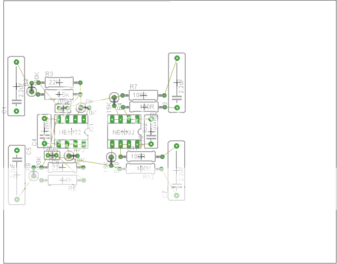
I've started the layout design. I'm using the free version of Eagle, 5.3.0.
This is just the preliminary parts placement layout; I haven't filled in the traces yet. The gnd trace will likely go around the outside of the parts; power traces will go down the center underneath the opamps. I want to keep it a simple, single sided board, and no jumpers should be necessary. I'll include multiple pads for the output caps so bigger sizes can be used. I used 12.5mm lead spacing for the resistors so 1/2W's will fit easily.
I think a gnd lift type circuit should be included on the PS board to keep the gnd on the preamp board "clean" (10R resistor and 2 1N4007's in parallel)...
Anything that should be done differently? Ideas?
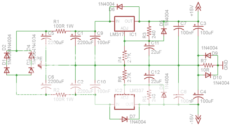
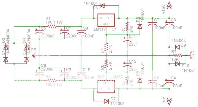
Power supply schematic... I just went from the LM317 datasheet and added the gnd lift circuit on the end. Output should be +/-15.3Vdc using standard values.
The gnd for the preamp board, and all the input signal gnds will return to this point, GND. PE will be connected to earth gnd. Is this the right way to do it?
The gnd for the preamp board, and all the input signal gnds will return to this point, GND. PE will be connected to earth gnd. Is this the right way to do it?
Make sure you use a "spur" off from the main reservoir caps as a clean ground to all circuitry. There are large circulating ripple currents in those caps that develop a volt drop across print and wiring that cause hum if you don't run a spur, and just connect "along the line" instead. That "star" point becomes the main signal ground. I wouldn't use ground lift resistors tbh... you shouldn't need it.
On your diagram the ground from C5 to C9 is "dirty" but to the right of C9 becomes clean. Make sure the "adj" terminals of the regs go to the clean ground.
On your diagram the ground from C5 to C9 is "dirty" but to the right of C9 becomes clean. Make sure the "adj" terminals of the regs go to the clean ground.
Attachments

yes,On your diagram the ground from C5 to C9 is "dirty" but to the right of C9 becomes clean. Make sure the "adj" terminals of the regs go to the clean ground.
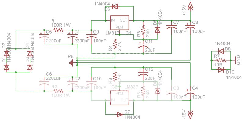
The common ground for C1, C2, C5 and C6 must NOT be connected to the zero voltage reference of the regulator.
The two halves of the circuit must have a separate ground lead to the Power zero volts point.
No.Like this?
You must break the connection between the smoothing caps zero volts and the regulators zero volts reference. The regulators require the C9 & C10 to be located at the reg. These must stay with the regulator zero volts line.
C3, C7, C11 and R4 must meet at a point. The zero volts reference.
Take separate wires from the regulator zero volts reference and from the smoothing caps zero volts to the main power ground.
Last edited:
Something like this. Your ground connection/s to the amps goes to the star.
Try and imagine and think of each wire and line of print as a resistance... and what will happen if a current (AC... but it's useful to think in DC terms too, to make it easy to follow 🙂) flows along it. Ask yourself "will it influence any other voltage or superimpose itself and interfere with any other part of the circuit"
The good news is that yours is such a low powered circuit it's not really going to be a major issue anyway... but it's nice to get it right.
Attachments

This seems completely unnecessary. Are individual ground runs really needed for each regulator? And one for each 100uF filter cap? Is this the same thing you were talking about, Andrew?
It's definitely not COMPLETELY unnecessary, although some parts are more important than others.
Currents flowing in ground return conductors induce voltages back upstream, at the non-ground ends of the conductors. So, something that should have a quiet ground should not share any length of ground-return conductor with something that is not quiet.
Conductors have at least both resistance and inductance. And while the voltage induced by the resistance is only the current multiplied by the resistance (bad enough; but it gets worse), the voltage induced by the inductance is the rate-of-change of the current multiplied by the inductance. If there are even small-magnitude currents that are changing rapidly, the induced voltage can be relatively large, with relatively-large dynamic fluctuations. And if that voltage appears back at the ground reference point for a regulator, or an opamp or amplifier input's ground reference, the voltage ends up being SUMMED with the input. That's "a BAD thing".
I have even read where people doing point-to-point wiring noticed a difference caused by the order/sequence in which ground lugs were stacked onto a bolt that was the star ground point, because of the added conductor length caused by the stacked thin ground lugs! So they made sure that they put the lug with the noisiest currents on the very bottom, so that those currents would share the shortest-possible path down the bolt with the other ground-return currents.
So, no, it's not completely unnecessary.
Cheers,
Tom
This seems completely unnecessary. Are individual ground runs really needed for each regulator? And one for each 100uF filter cap? Is this the same thing you were talking about, Andrew?
If you are aiming for perfection... then this is the way to do it. It's not just being fanatical about this... it's a very real issue and the main reason why DIY amps are not 100% silent hum wise (and a lot of commercial stuff too)
The charging currents in the main reservoir caps can be huge, they can peak in the "several amps" range for a millisecond or two. Now imagine you have a piece of PCB track or wire a few cm long that has only a few milliohms resistance lets say 10milliohms... and the current through those caps peaks at 2 amp. That gives you 20 millivolts of ripple. If you connect an input ground to that print and a feedback return a few mm futher along you have "introduced" a proportion of that ripple into the amp. Result... a harsh hum/buzz.
You can clearly see on a scope this ripple current just by clipping the ground wire to one of the reservoir caps and "sliding" the probe along the caps lead... it's very clear and measurable... and audible if you get it wrong.
In your case, you will achieve 98% of this by making sure you just keep the star ground separate as a spur from the main caps as I indicated earlier. It's all low power stuff... it's all essentially class A, so the current draw is constant. Is 98% good enough ?
When I started building amps getting them silent was the biggest problem... I just didn't grasp this earthing problem... and I was making the same mistakes all the time. When you sit and think, and think in terms of ohms law, and put in nominal resistances for all the conductors, you can then say " if 1 amp flows down there, will it in any way affect the signal"
As you have drawn it here, it's still wrong...
It works 🙂
indeed.As you have drawn it here, it's still wrong...
Listen.
Run a wire from the smoothing caps zero volts to the main audio ground.
Never put a string of tappings on the connection between the smoothing caps.
Regarding the ground lift resistor, it's placement seems wrong to me. Placing it between the PSU and audio circuit ground like that introduces a 10 ohm resistance to any circuit taking power from either rail and the ground, which is probably not what you want.
The idea of such a resistor is to prevent ground loops via the protection earth, so it should go between the device ground (the ground shared by the PSU and the audio) and PE. From electrical safety point of view, it's best not to have one and just directly connect to PE. Proper grounding of the equipment ensures that there is no hum due to ground potential differences. But what if the impedance via PE between devices is not much higher than along the interconnects? I would expect this to create crosstalk between (unbalanced) signals via magnetic coupling since PE acts as a signal return path. Also, RF pickup might result. I've never experienced this problem myself, so I can't say how big it is.
The idea of such a resistor is to prevent ground loops via the protection earth, so it should go between the device ground (the ground shared by the PSU and the audio) and PE. From electrical safety point of view, it's best not to have one and just directly connect to PE. Proper grounding of the equipment ensures that there is no hum due to ground potential differences. But what if the impedance via PE between devices is not much higher than along the interconnects? I would expect this to create crosstalk between (unbalanced) signals via magnetic coupling since PE acts as a signal return path. Also, RF pickup might result. I've never experienced this problem myself, so I can't say how big it is.
how about isolating the gnd of the reg from the smoothing caps
Attachments

Last edited:
how about isolating the gnd of the reg from the smoothing caps
So carry your idea foward 🙂
What value would you use ?
Where is the star point ?
If it's to the left of the resistor, then the reference pin of the regs are not accurately defined and with reference to the star would be subject to disturbance as any AC component flowed in the caps of the regs. That would alter both rails relative to the star even if the current draw was only in one reg.
If it's to the right of the star... where would you connect the load too... imagining it were a power amp etc ? The same problems of currents in the ground lead still apply.
Do you see 🙂
rightly or wrongly i assumed the load as being a power amps stage with its own dedicated supply.
in my preamp stage i have used a simple pre-reg from Rod Elliott's site here to drop the supply down to a regulator friendly voltage. I cribbed the resistor from this. Though i realise that this psu has its own transformer and smoothing caps.
Stormrider, I'm interested to know why you have selected a 22uf cap for c11/12
Hi Ted,
I imagine Rod is "trying to cover all bases" with the PSU in your link... he knows there will be lots of folk building it that don't wire the grounds correctly and that just connect them haphazardly. Ground lift resistors can help in those cases, but it's the basic layout that's wrong in the first place.
The easiest option is always to do it right first time 🙂 but that has to be designed in to a project as a whole.
Even commercial gear has problems, I have seen PCB's with "options" for different grounding schemes etc laid out on the PCB, and have seen official mods on commercial stuff that involves cutting print and wiring to different points.
It's a very difficult subject to grasp all the complexities of... those three pin regulators... you have to realise where the reference points are (what the output voltage is compared and referenced too) and that "modulating" that pin with ripple in relation to another point (a ground reference) in the circuit degrades the performance.
- Status
- Not open for further replies.
- Home
- Amplifiers
- Chip Amps
- Basic opamp based preamp