6A3 sUMMER, I am not sure that you got that right on the scope. First the input impedance of an oscilloscope is on the order of 10's of mega Ohms. Otherwise you could never measure a circuit because it would load it down. Now yes there is a balancing at the input stage of a scope but, it is only the balance in the differential amplifier and it is the offset at the input that cause the imbalance in the differential amp causing the beam to deflect away from the plates in the CRT. The only time balance that's used associated with a CRT is when you are actually inputting directly to the horizontal and vertical plates directly bypassing the input amps. That is how they create Lissajous Patterns. You know like the rolling circle at the beginning of Outer Limits... I have the manual to my Tek 7834 Quad input Storage Scope. It is also why you don't really want to try to do precise measurements with an old Eico or Heathkit scope. The input impedance is low enough it can effect small signal circuits. It would be like trying to measure a circuit, like the input of a lab quality scope with a Triplett Model 630 VOM instead of using a High Impedance DMM. Sorry but, it's true.
Regards,
Jamie
Regards,
Jamie
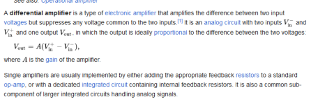
Chris,There is so much misunderstanding about this topic that it's very hard to know where to begin correcting all the "lore" that's accumulated. To begin with: how do we define "balanced"? - the term can mean several different things, and for inputs (ports receiving signal from the outside world) it has almost no meaning in modern context. For outputs it has two very different meanings, both called "balanced". Without defining terms we are stuck with lore, a poor substitute for knowledge.
All good fortune,
Chris
Actually balanced today is the same as what balanced was when Bell Telephone started stringing lines all over the US. There are 2 signal lines in each balanced cable. the signals , although identical, are 180 degrees out of phase with each other. There is also a shield around the cable. Now the reason balanced line or balanced is so effective is for a couple of reasons. 1.) because the 2 sides of the desired program material are out of phase with each other and because they do not actually interact with each other. When an outside signal( noise, hum etc), hits the cable simultaneously it cancels itself. 2.) One of the greatest advantages of a balanced line system is it acts as a low loss transmission line so you can have very long runs between amplification points without loss of signal. 3.) One of my points from earlier. Because the impedance of balanced line( being 600 Ohms) the other 2 components get swamped out having little to no effect. That is why the physical resistance is the dominate factor. You see it is true of everything have to do with AC theory. There is a Real and Imaginary component to any component dealing with AC theory and most of the time it is a complex Impedance that is every changing with frequency. Example: did you know that a speaker that is rated at say 8 Ohms, is actually only 8 Ohms at 1 given frequency and that is typically 1000 Cycles( Hz) and that is the point where the 2 Imaginary components ( Inductance and capacitance) become equal and cancel each other out and all that is left is the real component resistance. With capacitance, the lower in frequency the higher the capacative impedance( reactance) and it is opposite for inductance. I was going to post an image of what is known as a Smith Chart but, it is actually unnecessary. Chris let me just say this. One of my levels of expertise is R.F. ( Radio Frequency ) Engineering. A lot of people I worked with over the years say it's Black Magic. To this I say NO!! It's all " Simple Trick and Nonsense"!! The trick is to know what the Simple Tricks and Nonsense are. Now what I am going to say next is true whether we are talking about the power coming in on your wall socket to power you HiFi or the music you run from you player through a cable to you amplifier or when you answer you cell phone and it transmits you voice to the local cell tower. It is all AC and all the physical laws apply. And I have to stop and say. Thank you Nikola Tesla!!! Do you have any idea the absolute mess power distribution would be if Thomas Edison had won out and we decided to use DC for Power Distribution instead of AC. When you see power poles with wires running all over GOD's creation distributing power for our way of Life. They are called Transmission Lines and guess what? It's a Balanced Line system!!! So was our telephone system when we used Landlines!! A balanced line is this. There are typically 2 active lines together. At any given point on the lines at the equal distance, the electrical components are EQUAL an OPPOSITE!! So, in Modern Context it is as valid as it was over 100 years ago. If anything, I would ask you to clarify your statements from earlier. Tell me how balanced in receiving signals from the outside World is different from sending it from your High End CD player to you preamp. And please explain the 2 very different meanings pertaining to output. One statement I whole heartedly agree with you on is that "Lore" is a poor substitute for Real Knowledge!!! When I was dragged into High End HiFi in the late 90's I started a campaign to run the Carny Hucksters out of High End HiFi. I enlisted people like Eric Barber ( still one of the smartest guys I have ever met) and Kara Chafee the design Engineer for d'Havlind Amplification. Nothing but, silver wire and silver solder. Geez, now I am ranting but, think. I remember when they started selling ceramic insulators to the Audiophiles at ridiculous prices because you had to get you speaker cables up off the floor because to avoid damping from the Earth. Interconnect cables selling for more than $5000 a meter!!! And such stupid things as a Passive Pre-amp. For gosh sake it's a switch box with, I assume, is a level control for volume. Lastly , my favorite. The first year I went to CES which was about 8 months before we debuted Granite Audio at Stereo 98 in L.A. I walked into a suite and there was an older gentleman standing at the front of the room and he was playing music. At the front of the room in what I would consider the Sound Stage area were 2 flimsy wooden stands with 3 wooden disks on each. As the Music was playing, he would go to one of the stands and turn one of the disks and wait and then turn another one. After the song finished, he went to the guy I was with and said " did you hear the difference when I changed the disks"? Now my buddy had his press ID on him so, the man played up to him and my buddy just casually agreed and we started to leave. I told my buddy to hang on. I walked up to the gentleman and asked the list price for the stands and disks. $3000!!!! So, I asked my next question. " I am just wondering, di Home Depot give you a special price on those disks because, I can imagine that at 70 cents a piece it must really cut into your bottom line"!!! I agree with you the "Lore" has to cease but pick the right targets. If you don't understand the concept or concepts, ask but, be open and back it up by researching it yourself. Chris, I got into Electronics by way of HAM Radio but, I was also a Musician by that time. I was just ready to turn 11 years ol;d. I learned the Morse Code in a couple of weeks and with the Mentoring of 4 older gentleman I passed my first license. BNefore I turned 12, I got my General Class License. I started building and it is still one of my greatest joys today. Oh, yes, and I turned 70 last month. I don't know everything but, I sure have paid my dues and if you ask me a question I can't answer, I will tell you I don't know but, I have a pretty good technical library here at home and I will give my bes effort to find you an answer. I know I have said a lot. I hope some of it helped and if you clarify your statements, I will do my best to help your understanding. Best Regards, Jamie
From my modest experience with 3 differents balanced amps (with true balanced source), they tend to "sound" clean, little coloration.
Is it directly related to a different harmonic distorsion spectrum or isn't it that simple? I don't know.
Balanced, either between different boxes or within the same device has also the advantage of not using ground as a signal carrying conductor. Which not only eliminates the obvious hum producing ground loops, but also improves sound in more subtle ways.
Of course, as with everything else audio related the devil is in the details. Turning SE circuitry into balanced and back for the sake of adding a label is imo counterproductive and moronic. It is probably justified in profi audio but a bad idea with 60cm long interconnects. A number of reviews of dubiously designed equipment mention inferior sound quality through the balanced inputs/outputs.
jcalvarez So enlighten us or at least me. What is a balanced input/output in audio? I guess I really need to know this since I have been working with nothing but balanced I/O here in my recording studio since the early 80's!!! How do you think you get Common Mode rejection other that through the defination I just posted?
Jamie
Jamie
Attachments
Errr, I'm not contesting anything you said. I'm asking why it is really called "balanced" instead of just "differential". If somebody uses the term "differential input", then I don't have to think, I know what is that. If called "balanced", my mind translate that to "differential".calvarez So enlighten us or at least me. What is a balanced input/output in audio? I guess I really need to know this since I have been working with nothing but balanced I/O here in my recording studio since the early 80's!!! How do you think you get Common Mode rejection other that through the defination I just posted?
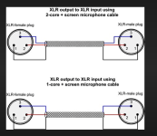
I don't know about inferior sound quality since it is the main stay of all recording studios and broadcast stations. Also if you look at the attachment, you will notice the the ground is connected on both sides. It is technically a part of the signal path because it is the return termination on both end. If you don't believe me try lifting the ground on either side of an XLR cable and see what happens.Balanced, either between different boxes or within the same device has also the advantage of not using ground as a signal carrying conductor. Which not only eliminates the obvious hum producing ground loops, but also improves sound in more subtle ways.
Of course, as with everything else audio related the devil is in the details. Turning SE circuitry into balanced and back for the sake of adding a label is imo counterproductive and moronic. It is probably justified in profi audio but a bad idea with 60cm long interconnects. A number of reviews of dubiously designed equipment mention inferior sound quality through the balanced inputs/outputs.
Attachments
I believe what analog_sa is saying (and I have seen the same thing) is some "Hifi" gear using XLR/balanced connections are doing a poor job of converting the output of the device from single ended to XLR to have than connection to market to the XLR connection only crowd. The one pre-amp I was talking about tested great on the RCA out, it was a disaster testing it on the XLR out jack. It's not saying the the connection technology is inferior, it's the implementation of it.
Ok, thanks for the clarification. That I can understand. I have seen a lot of really poor Engineering in this field. The truth is I have seen it in the Pro Audio field as well and that troubles me. It is almost like some Design Engineers have the attitude on some construction workers. They don't worry about the proper completion of the job because to quote... " You can't see it from my house"...
Now I get it.
Best Regards,
Jamie
Now I get it.
Best Regards,
Jamie
Now that I re-read this again. I do agree with the moronic comment. It's kind of like taking the replica of a Hummer body and putting it on a Suburban chassis and calling it really, really good and "Special"!! Makes almost as much sense as Tube Dampers.Balanced, either between different boxes or within the same device has also the advantage of not using ground as a signal carrying conductor. Which not only eliminates the obvious hum producing ground loops, but also improves sound in more subtle ways.
Of course, as with everything else audio related the devil is in the details. Turning SE circuitry into balanced and back for the sake of adding a label is imo counterproductive and moronic. It is probably justified in profi audio but a bad idea with 60cm long interconnects. A number of reviews of dubiously designed equipment mention inferior sound quality through the balanced inputs/outputs.
Regards,
Jamie
SO many incorrect posts, possibly a new record. THIS is what is correct: https://www.hairballaudio.com/blog/resources/diy-resources/balanced-and-differential
I don't think there is anything wrong with input transformers. But, in audio, every time you say "transformer", you must hear "high-quality transformer". Cheap input transformers that are added because the marketing department said "customers want XLR inputs on that amp" rarely qualify. (because the marketing department always add "do it without increasing the price")
It’s interesting to me that there would be XLR equipment that is not expecting a differential signal. Wouldn’t sending a differential signal to equipment not set up for it cause problems? In all my years I have never heard of XLR based audio equipment being incompatible with each other. The comments here make it sound like you’re more likely to get bad sound or have problems if you mix random XLR equipped gear.
To go back to my amplifier, it accepts a differential signal over XLR (what we mere audiophiles refer to as a balanced connection). Each phase of that differential signal is fed into its own driver and then on to the output tube where the push pull signal is combined at the output transformer. Did I get that right?
To go back to my amplifier, it accepts a differential signal over XLR (what we mere audiophiles refer to as a balanced connection). Each phase of that differential signal is fed into its own driver and then on to the output tube where the push pull signal is combined at the output transformer. Did I get that right?
"Posters",
You are all typing too fast, and I have been very busy lately. I will try and catch up eventually (But do not slow down for me).
wg_ski, Your post # 5 is my point exactly, XLR output eliminates the need for any kind of phase splitter within the tube amplifier; instead it puts the phase splitter in the signal source.
For those who misunderstood me, I never said there was no need for a phase splitter, but I alluded to the fact that the location does not have to be in the tube amp.
Jamiemuz, The impedance of a tube grid is variable.
The grid capacitance to other elements, as well as the Miller Effect Capacitance, cause variable impedance versus frequency.
There is a very small DC grid current that is due to the contact potential, and that grid current varies when signal is applied to the grid, because then the grid moves 'closer' to the contact potential, and moves 'away' from the contact potential.
Actually, the capacitance effects have Impedance; but the quiescent DC grid current by itself is resistive, it is not Impedance. Of course those two are in parallel, and we lump resistance and capacitance together and call it Impedance.
The grid return resistor to ground, Rg, is also in parallel with capacitance and DC grid current.
Thanks everybody for your inputs!
I will comment, hopefully soon.
This thread made me think of an idea I had years ago. Balanced, Differential, push pull without a phase splitter.
Take a CD player, re-design it.
Left channel: Use 2 DACs. Connect the 16 bits of digital this way: Cross-wire the 2 DAC 16 bit inputs, MSB of one DAC (1), to LSB of the other DAC (2),
then LSB of one DAC (1), to MSB of the other DAC (2).
That way, the phase of one DAC is 180 degrees from the phase of the other DAC. No need for a phase inverter.
Repeat for the Right channel.
Expen$ive, requires 4 DACs. But, who is counting co$t$?
Probably been done many times in commercial CD players, and diy CD DAC circuits.
Jamiemunz,
You said: "When you say clean, I will assume by that you do not notice any harshness in the spectrum."
I have 2 Lee Ritenour / Dave Grusin CDs, one of the guest singers is Renee Fleming.
I have always heard harshness in her voice on any system I was able to play that CD on . . .
Well, until now - I was surprised when I played those CDs on my Balanced Amplifiers. Clear, and Not harsh.
Just my expeience . . .
Every wire, and every cable, has R, L, and C. At some frequency (and at many frequencies), it is resonant, resistive, capacitive, inductive, or some combination of 2 of those 3. Frequency dependent, Yes!
Having worked in RF from 150kHz all the way to 40GHz, and waveguide extending from 3.5GHz to to 500GHz, I have experienced this fact.
Ooops, waveguide is not wire, and is not cable. But waveguide has R, L, and C; waveguide is not free space (and consequently waveguide's impedance is less than "free space impedance").
Last edited:
Jamiemuz,
I stand by my statements about early Tektronix oscilloscopes and plug-ins.
Just like the quick message that shows up very briefly at the beginning of the PBS Newshour . . . "Honest, Balanced, and Trusted".
Some balanced/differential plug-ins were 100k Ohms, and used 1X probes to get more sensitivity (10X probes have more bandwidth, but they destroy sensitivity; uV/division and/or mV/division).
I knew in 1962, that Tektronix oscilloscopes were legendary, my Junior year in high school.
In 1966 to 1968, I really wanted a Tektronix oscilloscope on our US Naval destroyer, the USS Braine DD630; sorry there was no such luck and no such blessing).
In 1968 I worked as a student summer hire at Tektronix; Test and Calibration for the 545B, with a razor trace so fine, even to youthfull eyes, you did not dare touch the CRT, you would cut your finger; and worked on various plug-ins; and I also had 6 weeks of Tektronix training on Tektronix circuits and concepts, during that 'summer' too - May to September.
Experience is one of the best teachers.
Last edited:
Balanced and Differential:
For those who forgot, there was 300 Ohm twin line (TV), and 600 Ohm ladder line (US military and Radio Amateurs).
Those did not have any shield around them.
But there is an electrical node that is equally spaced between the two wires.
300 Ohm twin line: The impedance from one wire to the node is 75 Ohms, and the other wire to the node is 75 Ohms.
Just like a 300 Ohm center tapped transformer, the impedance from one wire to the center tap is 1/4 the total wire to wire impedance.
600 Ohm twin line: The impedance from one wire to the node is 150 Ohms, and the other wire to the node is 150 Ohms.
Just like a 600 Ohm center tapped transformer, the impedance from one wire to the center tap is 1/4 the total wire to wire impedance.
Free Space impedance is 376.7 Ohms.
376.7 Ohms is higher than 75 Ohms, and is higher than 150 Ohms of one wire of twin line, and one wire of ladder line, to its center node.
And . . . the polarity of the two wires is 180 degrees out of phase, resulting in no radiation from the twin line / ladder line.
That is good, because twin line and ladder line do not radiate into free space, which lowers power loss, as long as there is nothing that is close to the balanced transmission line.
So, there is no need for: a shield, more material, weight, and expense.
How convenient!
Can anybody find me some 600 Ohm Ladder Line, I want to use it for speaker cable.
So the next time some audiophiles come over to listen to my latest stereo system with balanced amplifiers, they will see the ladder line.
:^)
Typical waveguide mode impedance is about 200 Ohms.
Waveguides are high pass filters, and below the cutoff bandwidth, the attenuation is infinite.
So I will not use waveguide for speaker cable.
Audio waveguide dimensions would have to cover the earth in order to pass the 6Hz canon of the definitive Telarc recording of Tchaikovsky's 1812 Overture.
^")
For those who forgot, there was 300 Ohm twin line (TV), and 600 Ohm ladder line (US military and Radio Amateurs).
Those did not have any shield around them.
But there is an electrical node that is equally spaced between the two wires.
300 Ohm twin line: The impedance from one wire to the node is 75 Ohms, and the other wire to the node is 75 Ohms.
Just like a 300 Ohm center tapped transformer, the impedance from one wire to the center tap is 1/4 the total wire to wire impedance.
600 Ohm twin line: The impedance from one wire to the node is 150 Ohms, and the other wire to the node is 150 Ohms.
Just like a 600 Ohm center tapped transformer, the impedance from one wire to the center tap is 1/4 the total wire to wire impedance.
Free Space impedance is 376.7 Ohms.
376.7 Ohms is higher than 75 Ohms, and is higher than 150 Ohms of one wire of twin line, and one wire of ladder line, to its center node.
And . . . the polarity of the two wires is 180 degrees out of phase, resulting in no radiation from the twin line / ladder line.
That is good, because twin line and ladder line do not radiate into free space, which lowers power loss, as long as there is nothing that is close to the balanced transmission line.
So, there is no need for: a shield, more material, weight, and expense.
How convenient!
Can anybody find me some 600 Ohm Ladder Line, I want to use it for speaker cable.
So the next time some audiophiles come over to listen to my latest stereo system with balanced amplifiers, they will see the ladder line.
:^)
Typical waveguide mode impedance is about 200 Ohms.
Waveguides are high pass filters, and below the cutoff bandwidth, the attenuation is infinite.
So I will not use waveguide for speaker cable.
Audio waveguide dimensions would have to cover the earth in order to pass the 6Hz canon of the definitive Telarc recording of Tchaikovsky's 1812 Overture.
^
Last edited:
- Home
- Amplifiers
- Tubes / Valves
- Balanced XLR input/output from tube gear