I notice most tube gear has unbalanced connections and the one piece of tube gear I tested that did have balanced jacks in addition to unbalanced, performed much better better using the RCA/unbalanced. I noticed when I opened it up, the XLR jacks were connected to some small transformers which I assume are what converted them to "normal" signals for the pre-amp board.
I haven't really studied this in depth yet, but my limited understand is most tube gear is not natively easily adaptable to balanced cables and use these types of transformers to convert that type of balanced signal into something they can process? I know I have rarely seen any tube schematics showing balanced connections.
Thanks in advance!
Te most popular solution for bal/unbal (and vice versa) is the transformer.
The truly balanced (symmetrical) implementation is rare, mainly due to the cost.
"Semibalancing" (unbalanced/balanced input, and symmetric tubes and output) is more common.

The truly balanced (symmetrical) implementation is rare, mainly due to the cost.
"Semibalancing" (unbalanced/balanced input, and symmetric tubes and output) is more common.
Attachments
Last edited:
Adding an op amp or two on each end on each channel to SS gear is no big deal. Adding two more triodes to make active balanced in/out is. Transformer is “easier” and does not contribute to noise. Unfortunately, flat frequency response in the transformers is not as cheap as good op amps.

stephe, euro21, and wg_ski,
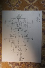
I am sorry for the sideways .PDF attachment, just print it out and turn the paper 90 degrees.
I decided to eliminate the input transformer in my balanced amplifier.
7 resistors at the input, but the shunt attenuator is only 3 resistors, the rest is 2 Rg to ground, and 2 grid stoppers.
A quality output transformer could be connected with the 4 Ohm tap grounded, and the 16 Ohm tap to the 'common' tap would give a balanced output.
Op amps, what op amps?
What is the difference? (pun intended)
Attachments
Last edited:
My Supratek Cabernet uses transformers to give balanced output over XLR jacks. I believe they are from Lundhal. Transformers also have the potential advantage of lowering the output impedance so that the preamp could be better used with more amps. I understand they aren’t cheap transformers but other than cost I don’t know what the downsides are.I notice most tube gear has unbalanced connections and the one piece of tube gear I tested that did have balanced jacks in addition to unbalanced, performed much better better using the RCA/unbalanced. I noticed when I opened it up, the XLR jacks were connected to some small transformers which I assume are what converted them to "normal" signals for the pre-amp board.
I haven't really studied this in depth yet, but my limited understand is most tube gear is not natively easily adaptable to balanced cables and use these types of transformers to convert that type of balanced signal into something they can process? I know I have rarely seen any tube schematics showing balanced connections.
Thanks in advance!
I spent the extra so that my push pull amp could be made without a phase splitter. I have nothing to back this up but my gut tells me that a (good) transformer phase splitter should give better results than an active one.
Most equipment is unbalanced inside, with or without valves. It just saves almost half the circuitry. Integrated circuits often use balanced circuitry inside, though: the extra transistors are cheap and the extra signal swing and cancellation of common-mode interference are quite welcome.
“So a push pull amp fed a balanced XLR input doesn't need a phase splitter?”
Right. In my amp I have a triode driving each output tube. Usually that’s a pair 6/12sn7 but I can use single triodes with adapters As well. Each phase comes in, is amplified and is sent to the output tube directly. It’s a really simple arrangement. I‘m not sure why it isn’t more commonly done that way.
Right. In my amp I have a triode driving each output tube. Usually that’s a pair 6/12sn7 but I can use single triodes with adapters As well. Each phase comes in, is amplified and is sent to the output tube directly. It’s a really simple arrangement. I‘m not sure why it isn’t more commonly done that way.
So a push pull amp fed a balanced XLR input doesn't need a phase splitter?
That's certainly one way of doing it, but some may object that such a connection lacks cmr at the input and poor balance between the phases.
Balanced or not should be a decision taken on a system level. Having additional circuitry for the sake of converting SE > BAL > SE is often counterproductive. And going balanced often changes the distortion spectrum, the tonal balance and certainly the soundstaging. Great if the result is to your liking but i know many who hate push pull in general and especially when it is combined with a balanced transfer of signal.
I have happily lived with a balanced source feeding a balanced preamp into differential input power amps, both SS and tube.
BAT has made this type of amplifier its signature for years. Check out their push pull amps. https://balancedaudio.net/
I‘m curious about the distortion, tonal balance, and sound staging differences. I would think that avoiding an active splitter stage as well as having simpler signal path could only help all those things. I think the sound I’m getting from my system is quite a bit more open and transparent than what I was able to get from a MC240 or a Jolida 6bq5 based push pull amp. What is it that people have objected to?
I‘m curious about the distortion, tonal balance, and sound staging differences. I would think that avoiding an active splitter stage as well as having simpler signal path could only help all those things. I think the sound I’m getting from my system is quite a bit more open and transparent than what I was able to get from a MC240 or a Jolida 6bq5 based push pull amp. What is it that people have objected to?
If you are willing to pay $7000 to $13000 for a phono preamplifier, the costs of a couple of extra valves don't matter much. The disadvantage that you need a quadraphonic volume control for a stereo preamplifier also doesn't matter much at $10000 to $30000 per preamplifier.
The simple explanation. Think about the input impedance of a vacuum tube. Have you ever seen a tube input stage with a grid resistor of anything less than 470K Ohms and typically more like 1 M Ohm. The comment about the input transformers is also correct. These days most manufactures are using 600 Ohm balanced transformers that have a 3dB bandwidth of around 100 to 300 Cycles( Hz) to , at best, 10 KC (KHz). Remember 3dB down is 1/2 power and it looses another 3dB every octave. So, at 150 Cycles, you are now down to 1/4 power. There are a number of alternatives and I would say not an op-amp. You have to get to know old equipment is one way. If you look for old input transformers on E-*** and such, there are a lot of all I can say is Yabos out there raking folks over the coals for like the little UTC or Triad transformers. Another possibility is to look for the old Shure 5 or 7 channel PA mixer like you use to find in Schools and Hospitals. I think the models are the Shure 401 and 701. Each input has a nice little aluminum covered , potted H frame transformer that rival the UTC's and Triad's. I think the last mixer I bought like that cost all of $40 and shipping was another $15. Now the secret is out so I can guess the cost of those mixer will now climb up. The transformers are board mounted and you have to be careful in de soldering or you will pull the pins out of the transformer. Another possibility is a little known fact that there are a series of Vacuum Tubes that have a spec'd working max voltage of 16 V. 12DW8, !2G8, for starters and then the 12U7 which has a 30V max plate. There are more but, I will actually have to dig in the book to find them. You will generally find these in among the sellers that bought up a bunch of tubes only to find out they were mostly off filament voltages or they were as these tubes were used in the last of the car radio before they went SS. Anyway, there is a couple of ideas. Typically, balanced lines were used for the primary purpose of Common Mode rejection. I have never looked at the concept of Balanced in as an elimination point for the phase splitter. There are some things I am just not that curious about. I have 2 different versions of the same basic amp. It used 6BL7's ( Dual power Triode) in the output. Both use a cathodyne phase splitter one uses a 6SN7 and the other a 12AU7. The other half of the phase splitter is used as a follower for the input stage. The input on one is a 6SL7 or 6SU7 and the other uses a 12AY7 or a 12BZ7. I do not use Global Feedback rather Degenerative Feedback.
Regards,
Jamie
Regards,
Jamie
I experimented.
First with single ended amplifiers: not to be discussed in this particular thread.
Then I decided to try 3 different forms of push pull:
I designed and built a self-inverting push pull amplifier: a single triode driver drove one of the output tube's grid, and the output tube's cathodes were tied together to a single current source to ground. That made the phase inversion occur in the output stage.
Then I designed and built another push pull amplifier, a dual triode with cathodes connected together to a single current source (a LTP phase inverter), their plates drove the push and pull output tubes grids. The phase inversion was in the driver stage.
Then I purchased a CD player with XLR balanced channels. The phase inversion is in the CD player.
I designed and built a balanced amplifier, 2 triodes driven from the XLR signal, those triodes drove the push and pull output tube grids. No phase inversion in the balanced amplifier.
Because I had good results in controlling input stage ground loops from un-balanced CD player to un-balanced amplifiers, I decided that I would not have to use a balanced input transformer. $ave money, and the frequency response was smooth and flat.
And there is no ringing from a resistive input circuit and volume control (no input transformer).
Hopefully that explains how I finally ended up with balanced amplifiers.
There is so much misunderstanding about this topic that it's very hard to know where to begin correcting all the "lore" that's accumulated. To begin with: how do we define "balanced"? - the term can mean several different things, and for inputs (ports receiving signal from the outside world) it has almost no meaning in modern context. For outputs it has two very different meanings, both called "balanced". Without defining terms we are stuck with lore, a poor substitute for knowledge.
All good fortune,
Chris
All good fortune,
Chris
Chris,
Great point about all the misunderstandings!
Check out an old late 1940s, 50s, or early 60s Tektronix single channel vacuum tube oscilloscope:
It used 2 probes,
A single channel plug-in preamp that was balanced all the way through,
And the scope main frame was balanced all the way through to the CRT vertical plates.
By the way, it used lots of LTPs tied to all those cathode pairs, for all those balanced stages.
I do not know of a better example of Balanced than that.
Of course you can also call all those stages Differential; because they qualify for both names.
And that is my Balanced Opinionated answer (pun intended).
When you say clean, I will assume by that you do not notice any harshness in the spectrum. One possibility for that is by having
a low impedance balanced line and all interconnections, you negate the effect of capacitance of the cable.
This also relates to the total bandwidth of the system. I was the design Engineer for a company called Granite Audio
back in the late 90's. When I designed the amps, I used no Global Feedback but rather Degenerative feedback( the simple explanation
lots of power supply and no bypassed cathodes). The amp was lab tested and the overall bandwidth with less than 1 dB ripple from end to end was 65 KC( KHz).
The power out in Pentode Mode was 60 Watts and in Triode 35 Watts. Also emk2, as far as Harmonic Distortion in a tube amp, the even orders tend to stand out more and as a result, the distortion tend to be in consonance with the programmed material rather than in dissonance. So, it become a matter of perception. back in the 80's there was a company known as Aphex. Their first product bankrolled the whole company and they became well known for recording and Live performance outboard equipment. The one piece of equipment was called the Aural Exciter. The concept was simple and I wish I had thought of it. You take a group of voices or instruments input it to the Exciter and the audio spectrum is split everything below 1000 Cycles( Hz) and everything above. The material below 1000 is passed straight thru the machine to the final mixer. Everything above 1000 is boosted up to clipping...ie... a square wave. A square wave is the presence of all harmonics basically. They would then filter it, and reinsert it with the signal below 1000. The harmonic insertion is lower than the below 1000 material but the effect is that now the voices are really bright and lilting and instruments become clean and crisp sounding with a whole new presence. So, what have they actually done? If you really look at it they increased the Harmonic Distortion!!! Think of this. You put a SS amp into clipping and it will rip the paint off the walls. You do the same to a tube amp and it soft clips and increases the even order harmonics. I know there is a lot here but, as simple as you might think. Going back to what I originally said,. balanced lines actually do 2 things. !.) it eliminates Common mode noise. 2.) the Capacitance in the low Z cables negates the effect of the capacitance in the cable. By doing that, you no longer have a tuned circuit that has an effect on the program material. After all a cable is a tuned circuit. It is unavoidable just by the laws of physics. A cable is actually a complex impedance. The wire in the cable has both inductance and resistance and the relationship of the different components in the cable are the capacitive effect. See now we are really getting in deep because now we have to talk about the relationship of those 3 components. The resistive component is considered the real component and the inductance and capacitance are known as the imaginary components. Why because their impedance changes with frequency. Sorry I got off on such a tangent. What I would say to you is this. What you hear in the 3 balanced amps and the rest of the components you really like. So, don't over think it. A joke we use to say was this . there are 2 types of people that listen to HiFi. The Music Lover and the Audiophile. The Music Lover listens to his Music through the system and the Audiophile listens to his system through the Music. Try to remember to be a Music Lover. I have been playing with and building this stuff since I was 11 years old. I am 70 and I still Love to just sit and listen to the Music. Regards, Jamie
- Home
- Amplifiers
- Tubes / Valves
- Balanced XLR input/output from tube gear