Yes the person who would like to build this and I looked at 4 gang pots, but the price is astronomical. We decided to use the shunt method instead.
The input impedance will not be very high here (12.5k minimum I think) but the builder is using a DAC so I think he will be fine with that source. The ECC99 has a high input impedance (100pf or so) so the shunt pot has to stay pretty low value, meaning the series resistors should also be low value (about 1/4 of shunt I think?), meaning the input impedance is relatively low value.
A lot of solid state stuff seems to have a 10k input impedance standard nowadays. At least this is a little higher than that.
I don't know why you will all center tabs wire to ground. The primary from the input transformer can float. Another thing are the resistors of the secondary side of the input transformer. What is your target you will reach with them? The signal that comes from the secondary of the input transformer is absolutly balanced. There is no need to work there with resistors. You can build it simpler with better results.
I mean all resistors exept of the grid stoppers. The grids has their potentials to ground over the secondary center tap of the input transformer. To implement an atennuator add one stereo pot in one channel (two stereo pots for stereo sound). Balanced is a simple thing...
Last edited:
You're also recommending to remove the input primary center tap ground? It could be put on a switch to lift it if needed, I guess?
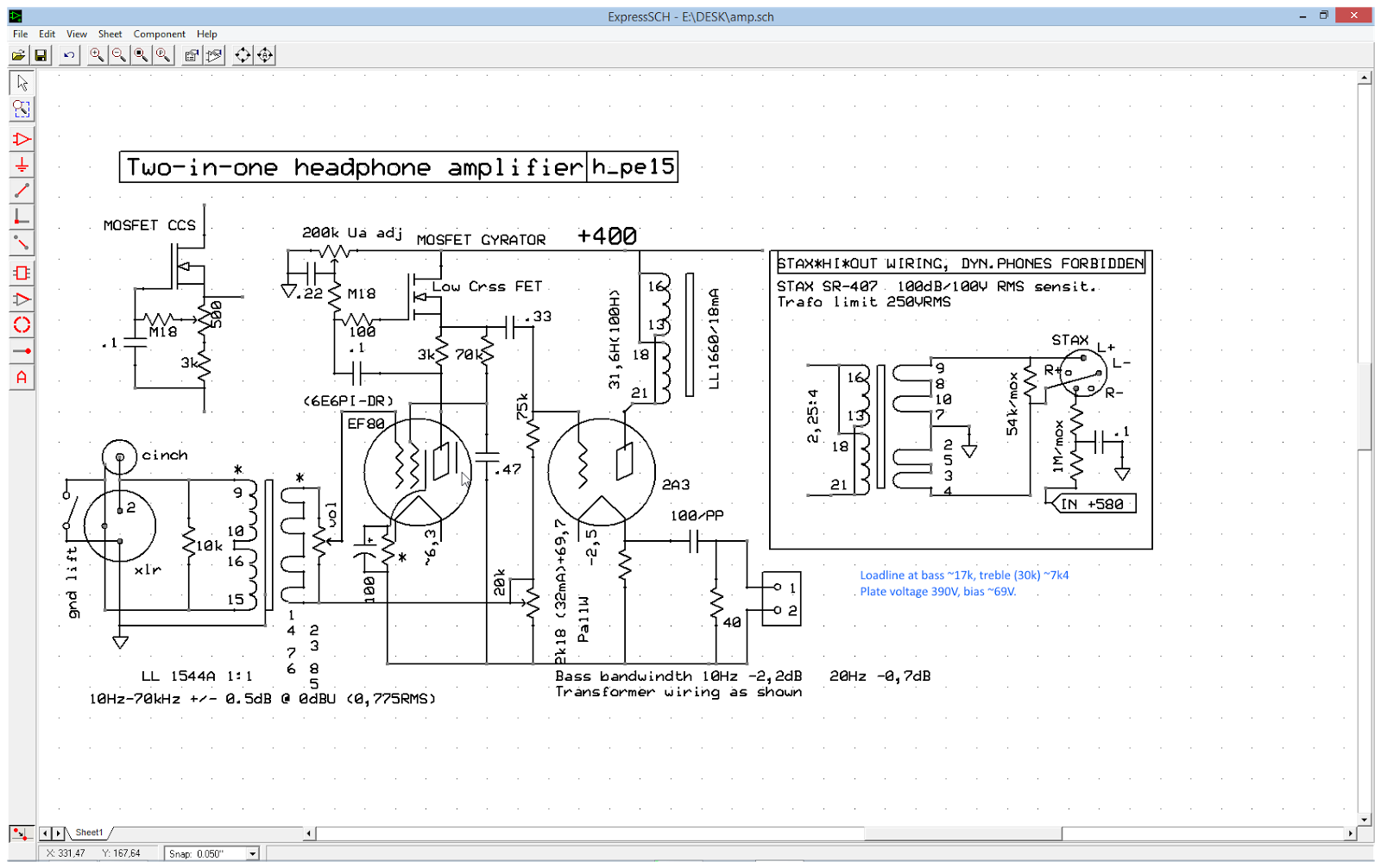
how about this
Do you know Lynn Olsons Raven? Thats the way to do it.... The Amity, Raven, and Aurora
Thanks, Dieter. I have looked at the Raven schematic a couple of times. I found this design using a shunt:
Active output
K&K also has a shunt kit at least:
K&K Audio | Raleigh Audio Line Stage
Have you had the chance to compare the sound of the two approaches in a circuit?
Edit: I should also mention that the shunt method is driven by cost. A four gang pot is not in the budget.
Active output
K&K also has a shunt kit at least:
K&K Audio | Raleigh Audio Line Stage
Have you had the chance to compare the sound of the two approaches in a circuit?
Edit: I should also mention that the shunt method is driven by cost. A four gang pot is not in the budget.
Sodacose I was playing with the very same idea about a year ago to make balanced headamp. However i saw you was thinking about no-feedback solution which I don't like.
I was developing project with small output transformers including quite high fully-balanced global negative feedback so the distortion would be minimal. It was inspired by MC275 fully balanced topology.
My result was unfinished project due to lack of time as I am really busy. So feel free to continue and maybe you will get inspired somehow:
I also have designed my own potted 1W PP output transformers with Raa=20k and Rz=32R and 250R + balanced feedback winding for this. but left unfinished on shelf
I was developing project with small output transformers including quite high fully-balanced global negative feedback so the distortion would be minimal. It was inspired by MC275 fully balanced topology.
My result was unfinished project due to lack of time as I am really busy. So feel free to continue and maybe you will get inspired somehow:
An externally hosted image should be here but it was not working when we last tested it.
I also have designed my own potted 1W PP output transformers with Raa=20k and Rz=32R and 250R + balanced feedback winding for this. but left unfinished on shelf
Last edited:
However i saw you was thinking about no-feedback solution which I don't like.
He is using hi-impedance opt+ triodes with good curves. Distortion not a issue here (unless the iron is junk); lower DF can give some bass bump.- Status
- This old topic is closed. If you want to reopen this topic, contact a moderator using the "Report Post" button.
- Home
- Amplifiers
- Headphone Systems
- Balanced Tube Headphone Amplifier?