Steve Eddy said:
Well no, you wouldn't see anything on the - line if you analyze it simply as drawn. That's because as drawn, it's not terminated. There's no load so the - leg is an open circuit with respect to ground.
Tie a load resistor across the two output terminals and then let me know what you see.
se
Only if you terminate it in a transformer.
Nelson Pass said:Only if you terminate it in a transformer.
How would terminating it in a transformer be any different than terminating it with a resistor?
se
Unbalanced
"How would terminating it in a transformer be any different than terminating it with a resistor?"
You are just kidding right? A transformer breaks the galvanic current (noise and signal return) conducted through the ground lead. I have reread this thread several times and I fear that it has created more confusion than edification (well maybe lots of eddyfication...) on the subject of balanced interfaces. There are factors that have not even been touched upon concerning signal currents on the ground lead and what actually causes common mode noise to begin with. Am afraid that the interface under discussion is not the only thing unbalanced around here. Do a web search or peruse a good engineering text book on your next trip to the bookstore for the real lowdown on balanced interfaces.
Val
Re: Unbalanced
Great. Now answer the question in the context it was asked.
If you read it several times and still could not catch the context of my question above, then there's something more than any "eddyfication" going on here.
Signal currents on the ground lead? What are you talking about? There is no ground lead. This is a balanced interface we're talking about here. Not an unbalanced interface.
<center>
<img src="http://www.q-audio.com/images/balanced2.jpg">
</center>
I'm at a loss as to why those who opposed your being banned did so claiming that you brought knowledge to these forums. Is this an example of the knowledge you bring here? "Go read a book"?
se
Val Lewton said:"How would terminating it in a transformer be any different than terminating it with a resistor?"
You are just kidding right? A transformer breaks the galvanic current (noise and signal return) conducted through the ground lead.
Great. Now answer the question in the context it was asked.
I have reread this thread several times and I fear that it has created more confusion than edification (well maybe lots of eddyfication...) on the subject of balanced interfaces.
If you read it several times and still could not catch the context of my question above, then there's something more than any "eddyfication" going on here.
There are factors that have not even been touched upon concerning signal currents on the ground lead and what actually causes common mode noise to begin with.
Signal currents on the ground lead? What are you talking about? There is no ground lead. This is a balanced interface we're talking about here. Not an unbalanced interface.
<center>
<img src="http://www.q-audio.com/images/balanced2.jpg">
</center>
Am afraid that the interface under discussion is not the only thing unbalanced around here. Do a web search or peruse a good engineering text book on your next trip to the bookstore for the real lowdown on balanced interfaces.
I'm at a loss as to why those who opposed your being banned did so claiming that you brought knowledge to these forums. Is this an example of the knowledge you bring here? "Go read a book"?
se
in the context it was asked
Sorry I guess I am a little confused about the context too. Anyone else? An active balanced circuit (as opposed to transformer) requires a ground reference. Most of the audio balanced interfaces have used have a plus, minus and ground conection using XLR connections. The ground connection is often used as a sheild also. For a little theory that might be beyond the scope of what is possible here:
http://www.dself.demon.co.uk/balanced.htm
http://www.balanced.com/faq/balanced.html
http://www.jeffrowland.com/tectalk6.htm
http://www.stagetec.co.uk/Pinout_pages/XLR3.html http://www.analog.com/library/applicationNotes/AdAudio/AN112.pdf
I also agree that a book is a great source to gain knowledge.
http://www.amazon.com/exec/obidos/ASIN/0672224526/avsearch-bkasin-20/102-5722608-7834506
Chapter 6 shows a balanced transformerless audio circuit simular to your last diagram WITH A GROUND REFERENCE CONNECTION for the input. Check it out.
Joe
Re: Re: Re: HUmmm
Why wouldn't the ground conductor carry the same interference/noise as the signal conductor? If the ground conductor of the unbalanced interconnect is attached to the negative input of the amp, I think you are still in business when the signals are summed.
The P1.7 schematic from the service manual only shows XLR connectors, so I can't really say what the connection would be.
JasonL: Why not just buy a balanced output CD player and make the whole discussion moot?")
Erik
Steve Eddy said:
Running unbalanced from the CD player to the Aleph P, the induced noise will be differential, rather than common-mode which means the Aleph P will simply amplify it and pass it on down the line.
se
Why wouldn't the ground conductor carry the same interference/noise as the signal conductor? If the ground conductor of the unbalanced interconnect is attached to the negative input of the amp, I think you are still in business when the signals are summed.
The P1.7 schematic from the service manual only shows XLR connectors, so I can't really say what the connection would be.
JasonL: Why not just buy a balanced output CD player and make the whole discussion moot?
Erik
Re: in the context it was asked
The output circuit and the input circuit each reference their own local grounds. There is no requirement that those two reference grounds be tied together.
The only reason you'd tie them together is as a band-aid to help amoeliorate problems caused by AC powered power supplies. Not for any requirement of the balanced interface. Personally I prefer to just get rid of the problem in the first place and leave the band-aids to Johnson & Johnson. But that's another story.
It's intended for a shield and is tied to the equipment chassis, not to fulfill any grounding requirement.
Have you had any experience with balanced professional audio gear? Much of it includes what's called a ground lift switch which allows the signal reference ground of the piece of gear to be disconnected from its chassis which is connected to the shield on the XLR.
Fine. However that doesn't change the fact that such a connection isn't any inherent requirement of a balanced interface.
se
JoeKnect said:Sorry I guess I am a little confused about the context too. Anyone else? An active balanced circuit (as opposed to transformer) requires a ground reference.
The output circuit and the input circuit each reference their own local grounds. There is no requirement that those two reference grounds be tied together.
The only reason you'd tie them together is as a band-aid to help amoeliorate problems caused by AC powered power supplies. Not for any requirement of the balanced interface. Personally I prefer to just get rid of the problem in the first place and leave the band-aids to Johnson & Johnson. But that's another story.
Most of the audio balanced interfaces have used have a plus, minus and ground conection using XLR connections. The ground connection is often used as a sheild also.
It's intended for a shield and is tied to the equipment chassis, not to fulfill any grounding requirement.
Have you had any experience with balanced professional audio gear? Much of it includes what's called a ground lift switch which allows the signal reference ground of the piece of gear to be disconnected from its chassis which is connected to the shield on the XLR.
Chapter 6 shows a balanced transformerless audio circuit simular to your last diagram WITH A GROUND REFERENCE CONNECTION for the input. Check it out.
Fine. However that doesn't change the fact that such a connection isn't any inherent requirement of a balanced interface.
se
Re: Re: Re: Re: HUmmm
They're not summed, they're differentiated.
And unless each line has the same impedance with respect to ground, then the voltage across it will not be the same and when the two lines are differentiated, the difference of the voltages across each line will not be rejected but amplified.
se
eLarson said:Why wouldn't the ground conductor carry the same interference/noise as the signal conductor? If the ground conductor of the unbalanced interconnect is attached to the negative input of the amp, I think you are still in business when the signals are summed.
They're not summed, they're differentiated.
And unless each line has the same impedance with respect to ground, then the voltage across it will not be the same and when the two lines are differentiated, the difference of the voltages across each line will not be rejected but amplified.
se
I'm soooo confused......
I just don't get it. I'll accept your statement that your passive implementation of your 'balanced' output circut will present a balaced impedence to a balanaced input circut, and externally imposed noise will indeed be common mode.... but your contention that one will have a balaced signal eludes me.
As I see it from my naive perspective, we have the positive signal, the output from the opamp passing through a voltage divider going to ground. We also have a mirror image of that voltage divider, originating at the ground leg of that op amp circut, going trough a series resistor (same value as the series resitor from the + opamp output), and shunted ( with the same value as its mirror shunt) to that 'signal' ground, i.e. we've got a voltage divider starting at ground and ending at ground.... so how the heck does a voltage divider starting at ground and ending at ground, have anything but ground at the midpoint of a 2 resistor voltage divider. I will admit its been 35+ years since I leaned Kirshoff's Law, but has it changed in the meantime? I'm not disputing that this termination does provide benefits in interfacing to a true balanced termination with regards to noise rejection (common mode rejection requiring equal impedences), but you previous contention that this will provide a balanced signal still eludes me.
Re: I'm soooo confused......
It eludes you because I didn't make such a contention.
As I said previously, "balanced" only refers to the impedances of the two lines with respect to ground. Whether the lines are balanced or unbalanced, the <b>signal</b> exits differentially between the two lines.
Now if you're referring to my having mentioned bipolar signals, i.e. +v and -v, that's easy enough to explain. You just seem to be looking at it from a different perspective than I am.
As far as I'm concerned, "signal" only matters at the receiving end, and that's the perspective I'm looking at it from. In other words, I'm looking at what the balanced, differential input at the receiving end "sees."
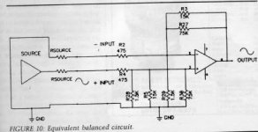
It perhaps wasn't quite so obvious from the last schematic I posted so let me simplify it it a bit on the receiving end:
<center>
<img src="http://www.q-audio.com/images/balanced3.jpg">
</center>
Does that make it a bit more clear?
se
pmkap said:I just don't get it. I'll accept your statement that your passive implementation of your 'balanced' output circut will present a balaced impedence to a balanaced input circut, and externally imposed noise will indeed be common mode.... but your contention that one will have a balaced signal eludes me.
It eludes you because I didn't make such a contention.
As I said previously, "balanced" only refers to the impedances of the two lines with respect to ground. Whether the lines are balanced or unbalanced, the <b>signal</b> exits differentially between the two lines.
Now if you're referring to my having mentioned bipolar signals, i.e. +v and -v, that's easy enough to explain. You just seem to be looking at it from a different perspective than I am.
As far as I'm concerned, "signal" only matters at the receiving end, and that's the perspective I'm looking at it from. In other words, I'm looking at what the balanced, differential input at the receiving end "sees."
It perhaps wasn't quite so obvious from the last schematic I posted so let me simplify it it a bit on the receiving end:
<center>
<img src="http://www.q-audio.com/images/balanced3.jpg">
</center>
Does that make it a bit more clear?
se
The following is from http://www.jensen-transformers.com/an/an003.pdf
I see a difference between this drawing and your drawing--the capacitors.
Do you think the capacitors are not important?
I see a difference between this drawing and your drawing--the capacitors.
Do you think the capacitors are not important?
Attachments
Do you think the capacitors are not important?
jh6you. thanks for a great link! It is ironic that a company selling transformers has such a good app note on active balanced interfaces. It is also interesting to note the use of a signal ground connection, even for one balanced interface containing a transformer. Note there is a difference in signal ground and chassis ground. The capacitors are important to prevent DC currents in transformer windings which will affect the linearity and sonics of many small transformers.
From
http://www.dself.demon.co.uk/balanced.htm
"Renders innocuous ground-loops, so that people are not tempted to start "lifting grounds" This tactic is only acceptable if the equipment has a dedicated ground-lift switch, that leaves the metalwork firmly connected to mains safety earth. In the absence of this facility, the optimistic will remove the mains earth (not quite so easy now that moulded plugs are standard) and this practice must be roundly condemned as DANGEROUS"
Both these links are required reading and should clear up misunderstandings about in what "context" some of the previous post were meant to be taken .
Joe
Nope....
I still don't get it.
.It eludes you because I didn't make such a contention.
Stuff and nonsense....
If you converted to a balanced output using the passive solution, you'd measure +0.5 volts on the + line and -0.5 volts on the - line.
You certainly did make such a contention. And if you wish to rationalize that comment by stating that it is only valid on the recieving end for a truly balanced input , I'll grant you that.
But please realize some folks might actually accept your statements without that obligatory grain of salt and backpedaling. Used as a phase inverter, with a dpdt switch, it will simply provide useless common mode noise to a single ended input as others, far more compentent the me, have pointed out.
Whatever.....
should have read
SE wrote-
If you converted to a balanced output using the passive solution, you'd measure +0.5 volts on the + line and -0.5 volts on the - line.
You certainly did make such a contention. And that contention is simply not true. if you wish to rationalize that comment by stating that it is provides a pseudo-balanced signal on the recieving end for a truly balanced input , I'll grant you that.[for the purpose of rejecting common mode noise only!]
jh6you said:The following is from http://www.jensen-transformers.com/an/an003.pdf
I see a difference between this drawing and your drawing--the capacitors.
Do you think the capacitors are not important?
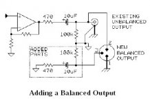
The capacitors are there simply because that's how Bill chose to represent a "typical unbalanced output." If the unbalanced output you're wanting to convert to balanced is DC coupled (i.e. uses no series output capacitors) then there's no reason to add any capacitors. If it's AC coupled, the example only serves to show that you need to mirror them on the other side of the circuit.
se
- Status
- This old topic is closed. If you want to reopen this topic, contact a moderator using the "Report Post" button.
- Home
- Amplifiers
- Pass Labs
- Balanced line