jh6you said:
Steve, take it easy.
Maybe I know what you are talking about ..., but I do not know why you are talking about... Let's go back to the interesting diyAudio dispute. Only for the technical dispute, PLEASE!!!!!!!!!!!!!!!!!!!!!!!!!!!!!!!!!!!!!!!!!
I am taking it easy.
Fred Deickmann is just the latest of many names used by the same person. I always looked forward to see what photo (or avatar if you will) he'd use for his next re-re-re-reincarnation. But this time he didn't use one and well, I was a bit disappointed and just a little curious.
")
se
 Good, man.
Re: un-bal
Even though there is no inherent requirement of tying together the grounds of balanced interfaces, not tying them together does have some negative consequences if the components are AC powered (as opposed to battery powered). In which case it would be best to tie them together.
But in order to implement the resistor scheme, you need to know exactly what the output circuit looks like in your preamp so you can determine the appropriate value resistors.
se
giolight said:Do you think I can fed the X Aleph from unbalanced pre with the Steve resistors scheme if I don't tie their ground together?
Giorgio
Even though there is no inherent requirement of tying together the grounds of balanced interfaces, not tying them together does have some negative consequences if the components are AC powered (as opposed to battery powered). In which case it would be best to tie them together.
But in order to implement the resistor scheme, you need to know exactly what the output circuit looks like in your preamp so you can determine the appropriate value resistors.
se
Nelson Pass said:Or you can put a pot at the source and trim for minimum
noise. I would say probably a 1K pot or so, maybe lower
or higher depending on the output impedance spec of the
source.
Yup. That'd work too. Though an AC-coupled output stage would make that solution alone a bit less effective and ideally you'd want to match any capacitance as well. But what works more ideally from a technical standpoint doesn't always give the most ideal subjective result so one should experiment for themselves and decide which is the more ideal for them.
se
giolight said:so if I understand I use the pot if the output source is not ac coupled otherwise I can use the pot to find the better value for no humming than substitute with resistors and add the cap and I can tie source and amp ground to hearth.
If I'm reading you right, that about sums it up, yes.
se
More X-former stuff
http://www.sowter.co.uk/acatalog/SOWTER_TRANSFORMERS_INPUT_TRANSFORMERS_9.html
What is it that Mr. Pass says?
bwaaahahaha...........
post-HH
http://www.sowter.co.uk/acatalog/SOWTER_TRANSFORMERS_INPUT_TRANSFORMERS_9.html
What is it that Mr. Pass says?
bwaaahahaha...........
post-HH
Banned
Joined 2002
JasonL said:soo..i can use this circuit then ill have to build to of them.. one per channel..
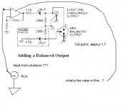
Um... no. In that diagram, the opamp circuit is merely there as an example of what's already inside your CD player. You're not supposed to create the entire circuit. Just the "added parts" in the dashed area.
Here, let's make it as simple as possible.
<center>
<img src="http://www.q-audio.com/images/adapter.jpg">
</center>
As Nelson said, simply adjust Rx (a 500 ohm or 1k trim pot will do) to match the output impedance of your CD player. If you can determine the output impedance of the CD player, you can simply replace the pot with a fixed resistor of the same value.
If you can figure out the output impedance of your CD player and use a fixed resistor, you could easily build it into a male XLR plug and run a pigtail with a male RCA jack on it to plug straight into your CD player.
se
- Status
- This old topic is closed. If you want to reopen this topic, contact a moderator using the "Report Post" button.
- Home
- Amplifiers
- Pass Labs
- Balanced line