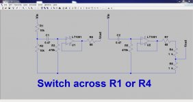
Here are two ways to do it. Switching grounds is never a good idea and the opamp needs a constant ground referenced bias to maintain the DC conditions.
The first one attenuates the input and the second the output. Both have there merits and disadvantages.
The first one attenuates the input and the second the output. Both have there merits and disadvantages.
Attachments
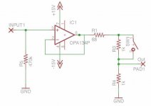
I would tend towards the circuit that attenuates the output, since none of
the orig. signal is lost. Wouldn't that one be more accurate?
What are the two resistors, R5 and R7 all about?
Here's an updated schematic w/o the coupling cap on the input.
Thank you Mooly
the orig. signal is lost. Wouldn't that one be more accurate?
What are the two resistors, R5 and R7 all about?
Here's an updated schematic w/o the coupling cap on the input.
Thank you Mooly
Attachments
The inputs are AC coupled for both circuits. That is good practice for most circuits because you just don't know what might get applied. The 470K defines the DC conditions for pin 3. It could be 1ohm or 100Meg ohm as far as the DC conditions are concerned. Make it to low though, and it will lower the input impedance. So 470K and 0.47uf is a good compromise. Together they form a high pass filter with a -3db point of 0.72Hz. The attenuator values (the two 10K's) are outside this filter and so can be altered at will.
The second circuit is similar at the opamp input side. The disadvantage of this circuit is that if the input is so large (such that it cause the opamp to clip) then no amount of attenuation on the output can correct that because the signal has already been distorted. The first one can attenuate any level on input and provide a distortion free output.
The 68 ohm isolates the opamp output from any capacitive loading. Some opamps can become unstable with light capacitive loads (sometimes oscillating at many 10's of Mhz). Its just good practice to include it unless you are 100% sure no issue exists by leaving it out.
What kind of an input impedance are we talking about here?
Ignoring the switch/divider network stuff, i calc. the impedance of your C1/R3 filter to be about 470k over the audio range which seems sufficiently high.
On of the reasons for using the op amp, besides adjustable gain, was as an impedance matcher for the drv134.
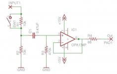
Ok next try..... This time i favor the 1st circuit after your functional explanation. After all, its all about attenuating an input that is too high w/o distortion/clipping! With the RC network on the input, guess i wouldn't need any additional capacitor here.
Because the op amp will be driving a drv134, which is close to the op amp, maybe i don't have to worry about capacitive loads, e.g. could omit the R4?
Btw. when the switch is closed, e.g. R1 is bypassed, don't I lose part of the signal over R2? But i guess even with R3 tied to ground, switching R2 away from its ground would also change the gnd. potential a bit, which as you pointed it is not a good idea.
Again many thanx Mooly!
Ignoring the switch/divider network stuff, i calc. the impedance of your C1/R3 filter to be about 470k over the audio range which seems sufficiently high.
On of the reasons for using the op amp, besides adjustable gain, was as an impedance matcher for the drv134.
Ok next try..... This time i favor the 1st circuit after your functional explanation. After all, its all about attenuating an input that is too high w/o distortion/clipping! With the RC network on the input, guess i wouldn't need any additional capacitor here.
Because the op amp will be driving a drv134, which is close to the op amp, maybe i don't have to worry about capacitive loads, e.g. could omit the R4?
Btw. when the switch is closed, e.g. R1 is bypassed, don't I lose part of the signal over R2? But i guess even with R3 tied to ground, switching R2 away from its ground would also change the gnd. potential a bit, which as you pointed it is not a good idea.
Again many thanx Mooly!
Attachments
What kind of an input impedance are we talking about here?
Ignoring the switch/divider network stuff, i calc. the impedance of your C1/R3 filter to be about 470k over the audio range which seems sufficiently high.
Yes, 470k is the input impedance of the opamp part of things.
The first circuit adds either 20k (10k +10 k) or just 10k (depending on switch position) across the 470k. In practice that difference is negligable.
So there's a "downside" to the first approach. The input impedance is non constant and "lowish". If the attenuator is fed from normal modern line sources such as CD players/DVD etc then its not a problem because all these can drive loads of that value easily.
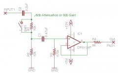
Ok next try..... This time i favor the 1st circuit after your functional explanation. After all, its all about attenuating an input that is too high w/o distortion/clipping! With the RC network on the input, guess i wouldn't need any additional capacitor here.
You should always have the capacitor
") Suppose the source had a significant DC offset. You don't want that passed down the chain.
Suppose the source had a significant DC offset. You don't want that passed down the chain.Because the op amp will be driving a drv134, which is close to the op amp, maybe i don't have to worry about capacitive loads, e.g. could omit the R4?
Maybe
The IC itself will present a capacitive load due to the internal semiconductor junctions... it may be a few 10's of pf's or several hundred pf. I have no idea unless the data sheet mentions it specifically. So good practice... assume there could be a problem.Btw. when the switch is closed, e.g. R1 is bypassed, don't I lose part of the signal over R2? But i guess even with R3 tied to ground, switching R2 away from its ground would also change the gnd. potential a bit, which as you pointed it is not a good idea.
With the switch closed all the voltage appears across R2. It doesn't lose any in that sense. If the source is capable of driving a 10k (such as the CD/DVD players etc) then all the output voltage of the player appears across R2
I will be driving this mainly from a preamp with output impedance of 47 ohms. I read somewhere that a good matching of input to output impedance is 100:1, so if that's true, in my case its 10,000:1So there's a "downside" to the first approach. The input impedance is non constant and "lowish". If the attenuator is fed from normal modern line sources such as CD players/DVD etc then its not a problem because all these can drive loads of that value easily.
The data sheet for the drv134 states the following:Maybe
Input Impedance: 10k
Should be driven by a low impedance source such as an op amp or buffer
Output Impedance: 50 ohms
Load Capacitance, Stable Operation, CL Tied to Ground (each output): 1uF
Not sure if that's "exactly" what u meant?
Short-Circuit Current: +- 85mA
Does the Short-Circuit Current spec. mean that both output signals, when shorted to gnd. pull 170mA max? In other words the absolute max current draw of the driver. Or do i got that all wrong?
Cheers,
Chris
 Chris, please be careful with the quote function. I have cleaned up a few of your posts.
 If the data sheet suggests it should be driven by a buffer then the first version is the one to go for. Keep the 68 ohm though.
I would take the short circuit current to be as you say in that each output can source or sink around 85ma maximum.
Your preamp sounds fine to drive any version. What really matters is whether the preamp can swing its full output voltage across the connected attenuator. For example a TL071 type opamp would allow a minimum load of around 2K and still be able to deliver full output voltage. Anything below that and the limited current drive ability of that opamp would limit the total outout available. Something like the OPA134 would happily drive 600 ohm load to full output.
Hi Mooly,
here are the lineout-analog specs of my preamp, from the manual:
output imp.: 47 ohms
output range, e.g. what i see on the display when turned down/up all the way: -90db/+15db
max analog out voltage: > 3.5 vrms or (9.0 vrms on subwoofer out)
analog freq. range: 2Hz - 20kHz.
I also took some measurements on the line out, playing a whole "track" from itunes on my computer.
itunes was turned up to about half way and my preamp was turned up to the max. volume setting.
Here's what i got:
Min voltage: 0.4
Max voltage: 620 mV
Avg. voltage: 260 mV
Seems to be a big diff., e.g. approx. 5 times, between whats specified as the max voltage and what i measured on some arbitrary music...
Are those numbers to be understood as peak to peak values, e.g. 3.5 => -1.75 - +1.75?
Cheers,
Chris
Studying the opa/drv134 data sheets and assuming a +- 15 rail supply voltage, e.g.:
OPA 134:
input: (V-) + 2.5 volts, (V+) - 2.5 volts => -13volts - +13 volts
output: (V-) + 2.2 volts, (V+) - 2.5 volts => -12.8 volts - +12.5 volts, load = 600 ohms
DRV134:
input: ? didn't find anything, well this isn't a pure op amp but rather contains 2 + other circuitry
output: (V-) + 2 volts, (V+) - 3 volts => -13 volts - +12 volts
Even with the max 9 volt rms output spec of my preamp for the subwoofer output, e.g. +- 4.5 volts,
I see no problems for my proposed circuit.
Cheers,
Chris
Your latest and greatest is fine... but you don't need C2 C1 does it all and can be kept as a small film/poly type.
Your preamp I'm sure will be just fine too.
(Try and understand the output impedance/input impedance/voltage drive thing If you take an opamp and configure it with feedback as here then the output impedance is always really low, perhaps fractions of an ohm. Working alongside that is the fact that the opamp also has a limited maximum output current. Whether that value is 1 milliamp or 100 milliamps, it doesn't affect the output impedance as such. What that current limitation does affect is how much voltage the opamp can put across a given resistance. When that current limit is reached, the voltage output from the opamp levels off... it can't increase anymore)
So as far as driving the DVR134, any normal opamp will easily manage the 10K impedance. The 68 ohm actually raises the output impedance of the circuit as a whole from <<1 ohm to 68 ohm. That means that for 10 volts output from the opamp, you are losing around 67 millivolts across the 68 ohm. So the DVR 134 sees only 9.9325 volts across its 10K input impedance. That loss is negligable and its linear (certainly over the audio band and way way beyond). The benefit of including the 68 ohm is the guaranteed stability it brings.
As to driving the 10K (worst case) input impedance of the attenuator you preamp has to be able to maintain its maximum output voltage (whatever that may be) across 10K. As its solid state it will probably use -/+ rails of an absolute max of -/+22 volts more probably -/+ 15 or 18 volts. Lets say 22 volts and that it can swing to 22 volts. That means it has to be able deliver around 2.2 milliamps into 10K. Yes Its sure to be able to manage that.
9 Volts RMS that you mentioned is 12.8 volts peak (25.6 peak to peak) so that implies rails of 15 volt. Its not -/+ 4.5 volts That level will be OK with your OPA134 running on 15 volt rails.
C1 does it all and can be kept as a small film/poly type.Your preamp I'm sure will be just fine too.
(Try and understand the output impedance/input impedance/voltage drive thing
If you take an opamp and configure it with feedback as here then the output impedance is always really low, perhaps fractions of an ohm. Working alongside that is the fact that the opamp also has a limited maximum output current. Whether that value is 1 milliamp or 100 milliamps, it doesn't affect the output impedance as such. What that current limitation does affect is how much voltage the opamp can put across a given resistance. When that current limit is reached, the voltage output from the opamp levels off... it can't increase anymore)So as far as driving the DVR134, any normal opamp will easily manage the 10K impedance. The 68 ohm actually raises the output impedance of the circuit as a whole from <<1 ohm to 68 ohm. That means that for 10 volts output from the opamp, you are losing around 67 millivolts across the 68 ohm. So the DVR 134 sees only 9.9325 volts across its 10K input impedance. That loss is negligable and its linear (certainly over the audio band and way way beyond). The benefit of including the 68 ohm is the guaranteed stability it brings.
As to driving the 10K (worst case) input impedance of the attenuator you preamp has to be able to maintain its maximum output voltage (whatever that may be) across 10K. As its solid state it will probably use -/+ rails of an absolute max of -/+22 volts more probably -/+ 15 or 18 volts. Lets say 22 volts and that it can swing to 22 volts. That means it has to be able deliver around 2.2 milliamps into 10K. Yes
Its sure to be able to manage that.9 Volts RMS that you mentioned is 12.8 volts peak (25.6 peak to peak) so that implies rails of 15 volt. Its not -/+ 4.5 volts
That level will be OK with your OPA134 running on 15 volt rails.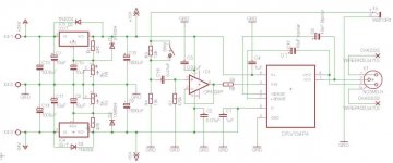
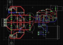
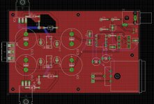
Board Layout, 1st Try
Thanx Mooly for your great help and motivation!
Now I'd like to begin with the board layout...
This is my first attempt at making a PCB, so pls. bare with me.
I'm sure there's lot's of room for improvement.
I'm using eagle to do it and the board has two layers as can be seen by the blue and red tracks.
The thick tracs for power and Gnd. are:
0.066 wide
The thin tracs on the amp / drv. side are:
0.032 wide
I haven't added any ground plane(s) yet. I will post the first version here w/o any. I would think that after adding the ground plane, some of the ground tracks would disappear and the resulting layout would become simpler.
Should i add two, e.g. top and bottom?
Cheers,
Chris
Attachments
- Status
- This old topic is closed. If you want to reopen this topic, contact a moderator using the "Report Post" button.
- Home
- Source & Line
- Analog Line Level
- Balanced Line Driver with DRV134