While waiting for the parts we could read this NwAvGuy: Op Amp Measurements
When done reading the previous then start at this one http://www.sg-acoustics.ch/analogue_audio/ic_opamps/pdf/opamp_distortion.pdf
Copied from the MPP-thread (it needs to go here (I think)) ")
You could glue the smd (using double sided sticking tape) to the middle of a dip socket/header and use some thin (silver?) wire to connect the smd to the pins, while working under a loupe.
Got all the bits for it box and all will have to do that when listening to FiFi is not possible (tely on neighbours in).
TT is already wired for balanced as I had INA LT1028 X5 X2 split passive RIAA
before.
Give me couple of weeks and it shuld be done.
Only scary bit is SMD to DIL part but I duble up on spares and have couple of presents from Analog devices to exercise on.
You could glue the smd (using double sided sticking tape) to the middle of a dip socket/header and use some thin (silver?) wire to connect the smd to the pins, while working under a loupe.
I would like to see yout wire bender Frans
Nice work bksabath
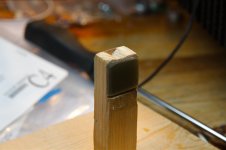
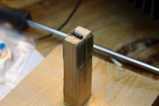
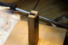
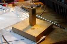
Here it is, the (c) FdW 'Wire bender'
it makes nice 'square'-bended, and 'un-stressed', very even (sized) bended-resistors.Attachments
Last edited:
Super cool... I will build one ASAP... I am actually working in a "Menuiserie" so I can have easy access to all sorts of wood and corresponding machines.... (I am also considering building a pair of speaker enclosures
I'm sure that the speakers will be the easy part
thanks for like-ing it 
Can't see anything wrong
BTW you need a resistor wire bender, I will post a picture of mine later today.
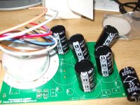
There is one thing wrong, IMO you should first have done the full build of the raw, then the pre- and then the clean power supply, this to be enable you to test each step before connecting the next step. By building the input stage very early you risk (there is not much risk
) it at every step of the way.Yes I know never got around to get one
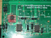
Still I am pretty made up with the smd welding
Now that I got around to it is pretty easy
Just a bit of solder paste on track and hold chip with crocodile clip
Just touching with wet solder tip does the trick
About SMD. I do like non-SMD, old school through-hole, constructions, and I like them spacy
, not maximum compact. IMO spacy circuit’s sound better than very compact, as normal for SMD constructions, circuits.Quite right
Just bit and pieces out of stock or Postman waiting for house to be empty
I can not wait to see/get a listening report from you
I can not wait to see/get a listening report from you
Right no presssure then
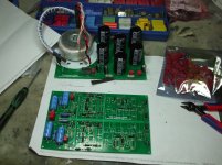
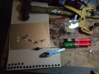
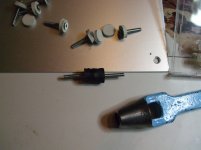
Today I have been making those
Shuld take care of same vibration when mounting PCB
Attachments
Right no presssure then
Today I have been making those
Shuld take care of same vibration when mounting PCB
Nice, I did mount my boards on nylon struts and bolts in the boxes, then the boxes are mounted on separate nylon struts and bolts to a 'floating' sub-frame, floating (not truly) by being flexible. Due to the high mass of the 2mm thick copper box the whole system is mass-dampened.
- Status
- This old topic is closed. If you want to reopen this topic, contact a moderator using the "Report Post" button.
- Home
- Source & Line
- Analogue Source
- Balanced input all DC coupled RIAA preamp