will there be any problem using 2SK1529/J200 in this amp in place of 2SK1530/J201? I only ask, because I have a small bag of them left from another project and from what I can see at least its close enough to have to ask if there is something i'm not seeing. being that they are of the same family, with the main difference being a slightly smaller package and lower current handling. still within spec for this build I would imagine and the lower capacitance of the smaller pad might be an advantage. I will have ample heatsinks, i'm using keratherm red isolators, so seems it should be alright. perhaps the sonics are not as good Patrick? I have not used its larger brother so dont know.
i'll be driving ~6-8ohms 2 ways
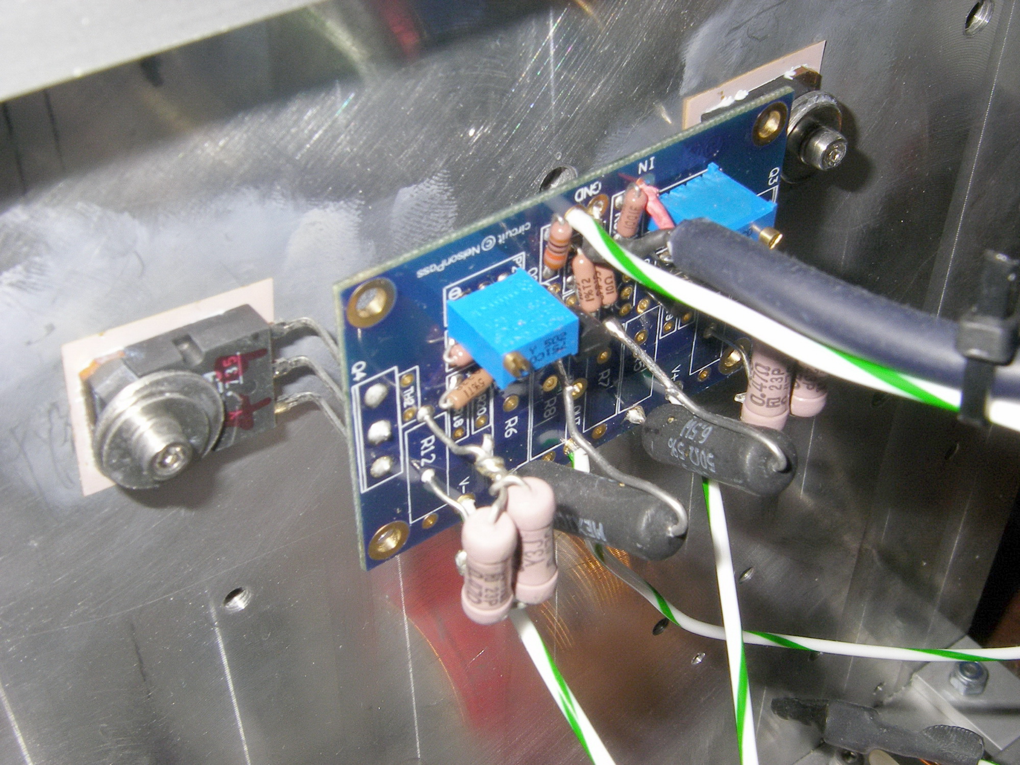
Here is a picture (not balanced F5)!
Almost a year, I am using 2SK1529/J200 without thermistor & current limiter, I like them better than Fairchild mosfets!
Biased at 1.75A and 8oC-10oC (kapton isolators) difference between heatsink and mosfets!
An externally hosted image should be here but it was not working when we last tested it.
Inrush calculation check
I posted a form of this question on the PS forum, but didn't get any answers.
I'm accustomed to the NTC (CL-60) that NP uses for the F5 PS. In looking at a PS for the Balanced F5, I could not tell if a different NTC was appropriate. I've read through the various calculations, the one area I couldn't really understand was Cmax.
I was considering two 500VA toroids with 120V primaries and 15V secondaries.
I used the Ametherm website and tried to fill in the blanks.
On Imax, they suggest 120V input (170Vmax) and I thought I'd be OK with 10A max yielding a 17 ohm NTC.
Many of the NTCs list a Cmax of around 300-5000uf. If I have 108,000uf in filter caps, how many joules do I need to worry about? Is it simply Joules=.5*(.108)*20^2? Or about 21 joules? That seems quite small.
Finally, if I use 500VA toroids, is the calculation of maximum constant current as simple as =500/120*.9 (efficiency) or ~4.6A?
In conclusion, an NTC with 17ohm resistance, able to handle 21J, and 4.6A steady state is proper?
Last edited:
NP, thanks for the input.
The CL-30 is 2.5 ohms. Do you use them in series?
The CL-30 is 2.5 ohms. Do you use them in series?
I would use one for each transformer.
I'm pretty casual about the calculations on the thermistors -
with FW I use one CL60 with 240V operation and one for
each winding on the parallel 120V primaries.
For larger products, we use CL30's.

the smaller To3p package is not so good at dissipating heat.
If you build using the smaller package and ask it to dissipate the same heat, it will run hotter. This will result in less reliability. I cannot estimate whether it might reduce life from 100years to 50years or from 10years to 1year.
If you reduce the heat by reducing the PSU voltage and/or reducing the bias current so that Tj is the same in both packages, then reliability should be restored.
Thanks Andrew, yeah I figured lowering the rails slightly might be a consideration due to the smaller pad, its an advantage one way WRT capacitance and likely bandwidth, but as you say cannot lose as much heat.
but if that is the only thing I need to worry about I can cope with that, I will build as specified and measure temp, if there is a very small issue I will lower the rails and bias current, if there is more than a minor reduction needed then I will simply replace with K1530/J201.
Dazed and BigE.
Do more research.
I'll start you off.
Vac is not the same as Vdc
If the amplifier is to run on +-20Vdc you do not use a 20+20Vac transformer.
20Vdc/sqrt(2) = 14.14Vac Use a 14Vac or 15Vac transformer.
Power distribution.
The power distributed either from the mains or within your amplifier is governed by the formula Power = Volts * Amperes.
Sometimes Volts and Amperes are not quite in phase. So we use VA = Volts * Amperes.
If you have a 600VA transformer and want to connect it to 110Vac mains then the maximum primary current is defined by the same formula but rearranged.
Max I = Max Power / applied voltage.
Imax = 600VA / 110Vac = 5.45Aac (this calculation assumes transformer is 100% efficient. If we know the 600VA is 93% efficient then actual primary Max I = 5.45 / 0.93 = ~5.9Aac
Use a T5A or T6A fuse to run this transformer up to it's maximum continuous rating.
But, there is a problem.
The fuse will often/sometimes blow when you start up the amplifier.
You need to add a soft start to allow the fuse to pass starting current without nuisance blowing.
This gives you a number of starters for your reading/homework.
I built a 1.2kva balanced power supply using a toroid.
To start the toroid, I bought a Microprocessor controlled soft start relay. It allows the power to ramp up from 0V to full voltage over one second. It's a bit expensive at $100, but I sleep well at night.
It is made by crydom, and is in their MCS series. I got it from mouser.
I cannot estimate whether it might reduce life from 100years to 50years or from 10years to 1year.
Use simple rule of thumb: 10 °C more heat means half lifetime.
Hannes
The CL-30 is 2.5 ohms. Do you use them in series?
No. We have a switch/breaker with a large surge capacity.
On the higher power units we don't want the losses of a
higher thermistor value.
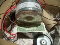
Pictures please

Only a true DIY'er can get excited about pictures of a transformer...
My transformers probably won't show up for a couple more days over here on the west coast, so yes pictures please...
Attachments

Wow--you mean, you even got a stack of $1 bills, with your transformers? Nice.....
If you are in Western New York state, I'm guessing you'll have a LOT of time to build the amp, before you get your Spring Thaw!
Nice tranformer!
Wow--you mean, you even got a stack of $1 bills, with your transformers? Nice.....
Nice tranformer!
Yeah! The dollar is so weak the Canadians use it for packing
Yeah! The dollar is so weak the Canadians use it for packing
Be thankful your not from Zimbabwe, their currency is used for heating

- Status
- This old topic is closed. If you want to reopen this topic, contact a moderator using the "Report Post" button.
- Home
- Amplifiers
- Pass Labs
- Balanced F5 question