This is mich simpler: You built the ccs with a variable potentiometer, just order from kandkaudio the kits which are really inexpensive.
It takes 10 minutes to wire this up on perf board...
Using low mu valves in an LTP requires the use of a CCS tail. This is because the degree of unbalance in an LTP with resistive tail varies like 2/mu (IIRC).
Not with a balanced input...takes four sets of volume pots though.
there is also 6AH4, a single triode octal with a mu of 8.
cheers,
Douglas
¨I could never successfully reconcile all the conflicting requirements for a diff stage. <snip>
I think it is quite feasible to do it without a negative supply when using low-mu (DHT) tubes. Having the grids at GND level (driven from the low RDC of an input transformer used as phase splitter), the cathodes of a 10Y will sit at maybe 10-20VDC (havent looked at the datasheet, sorry). Ohms law dictates the needed resistance to keep them at this operation point, and I would imagine that using low RDC chokes from Lundahl one can become quite some inductance for the needed resistance.
Erik
Unless you go for the shortened ball-att version which is self-balanced.Not with a balanced input...takes four sets of volume pots though.
Don't really understand how important is the degree of disbalance in practice. I have left the input of the power amp to deal with this. Expected elevated second harmonic due to the imbalance but cannot really measure any, perhaps because of the transformer pp action.
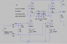
The circuit shows a SE output but in reality it is connected as BAL. R7 is a rheostat.
Attachments
Erik, Intersting idea...but how do you bring the cathodes to 10-20V ? One Resistor like in the Karna from L. Olson ? http://www.nutshellhifi.com/Karna.gif
Ok, but then we have only a differential pair with a non-perfect symetry as the Load resistor is quiet low compared to the impedance of a CCS...and especially for low mu tube you want a high impedance, dont you ?
I have build a diff. line stage for my DAC with 4p1l and 10y, currently running 801a. I still have to experiment with the CCS portion though, so far just ised Kevin's Carter CCS (yes you can build them on a billb. in 10 minutes, but Kevin's board are just perfect, small, professional and cheap; its more work to do the job without his kits, saves me time).
As raw supply I used a LDO reg ultra-low noise etc. Nevertheless, I still want to test a hybrid version with a tv damper tube as those types need only 40V headroom...
But I can see completely the point of using everywhere polyprop caps instead of lytics, going LCLC with amorphous cores etc in the b+ or with DHTs as well in the heater and finally you add silicon and lytics theough the negative supply...not my dream either, but I have not found a better solution yet.
Different story when two stages are there and dc-coupled. grid of second tube is elevated to anode level of the first one...so...we have enough headroom for the CCS plus the grid-cathode voltage plus the signal swing.
I never thought about this and never have seen a schmatic where the same theory has been applied to only one stage to get rid of the negative supply...but lets take this example of an 10y:
At 300V, we need about -10V for the grid at approx. 30mA. The CCS needs 15V to operate, the signal swing is maybe 1V, the headroom for the filament difference is 7.5V/2 as this is a DHT. So, we need approx. 10+15+3.75+1 giving approx. 30V total headroom. Add a tv-damper and it will be 70V.
So, we need to shift the whole psu by 70V up: Anode 370V, grid 60V, Cathode 70 (middle point), cathode of tv-damper 30V, Bottom of CCS 0V.
The price to pay for this would be a new coupling cap for the grid I am afraid. So which devil is worse ?
Last edited:
Hi Blitz,
we already exchanged some ideas regarding this in post 26 and 27.
The idea is that indeed one replaces that resistor (as in the Karna) with a choke with similar DC resistance and gapped for the required current. The DC resistance sets the idle operation points while the inductance provides for a higher load. You did some calculations on that already")
I would use the splitting transformer at the input, so the stage already becomes a balanced input signal. Theoretically that would not even require the choke in the cathodes anymore (Lynn Olson is not using them as well, just plain resistor), but the choke would certainly change the operation characteristics (for example better isolation from PS, true differential operation) that the end result will be different than the plain resistor.
I have never done this myself, as I do not have wideband chokes at hand (and try to reduce the use of iron as much as possible).
we already exchanged some ideas regarding this in post 26 and 27.
The idea is that indeed one replaces that resistor (as in the Karna) with a choke with similar DC resistance and gapped for the required current. The DC resistance sets the idle operation points while the inductance provides for a higher load. You did some calculations on that already
I would use the splitting transformer at the input, so the stage already becomes a balanced input signal. Theoretically that would not even require the choke in the cathodes anymore (Lynn Olson is not using them as well, just plain resistor), but the choke would certainly change the operation characteristics (for example better isolation from PS, true differential operation) that the end result will be different than the plain resistor.
I have never done this myself, as I do not have wideband chokes at hand (and try to reduce the use of iron as much as possible).
Nevertheless, I still want to test a hybrid version with a tv damper tube as those types need only 40V headroom...
Please do tell if you try this. It did not work well for me. Perhaps at low voltages these tubes require a more substantial current draw to sound good.
Will report back...
Thx for the reminder...I need to see what Lundahl Iron I have in my stock, I bought a complete batch from ebay, all kind of stuff...price was ridicolous low.
I guess this choke-idea was stuck when it comes to the relationship of how much current needs to go through it vs. how much resistance vs. inductance you get....but still something on the list...(which is quiet long...)
- Status
- This old topic is closed. If you want to reopen this topic, contact a moderator using the "Report Post" button.
- Home
- Amplifiers
- Tubes / Valves
- Balanced Differential Linestage with Low Mu - perhaps DHT ?