I certainly hope they sound better than they look!
This is match to play with burning hockey puck
")
Congratulations have a mosfet winner game

Attachments


The screws and washers come with the pucks from Mouser in a separate bag. Still working out how many ring terminals I need to be piling onto each screw based on the PS cap configuration.
Cool.
I did that for the F5T. Takes forever. Copper bus bar might be quicker.
Cool.
I did that for the F5T. Takes forever. Copper bus bar might be quicker.
Thanks for the heads up! I did a copper ground plate for a refurb recently and it was painful but worthwhile in the end - I have to look at it everyday and if I didn'g do it "right", probably kick myself over and over.
The first job is to get the heatsink config nailed, before deciding wire topology. I am waiting a quotation from Austerlitz on their KS216, since a 50cm piece of it would dissipate the 200W this beast makes by -30°C. And it'd double nicely as the back of the amp "case", which is actually being conceived as a speaker stand for my 15" tall speaker.
Attachments
we have a nice example for using the optocoupler for biasing an output stage and even the LTP already here in the Pass Labs forum by Nelson himself
http://www.diyaudio.com/forums/pass-labs/262367-mu-monster.html
The Mu Monster is such a nice idea……
OK. Thanks for that.
O.k......
I was more delighted to see the use of the optocouplers in the outputstage and in the LTP than in the adventure to build this really........
I have a big case from a friend with big heatsinks so ........
Do I want to play hockey.....?
I'll be definitely referencing that circuit at some point in a future build although heavily scaled down. Probably 3 pairs at output biased at 1A each with 22 to 30V rails. Maybe throw Cree devices at the output. Toshiba Jfet input.
Or maybe even throw a single pair of hockey pucks at it
Last edited:
The first is done with Nelson's circuit with IXYS hockey puck.So the first was not done with the circuit Nelson showed...?
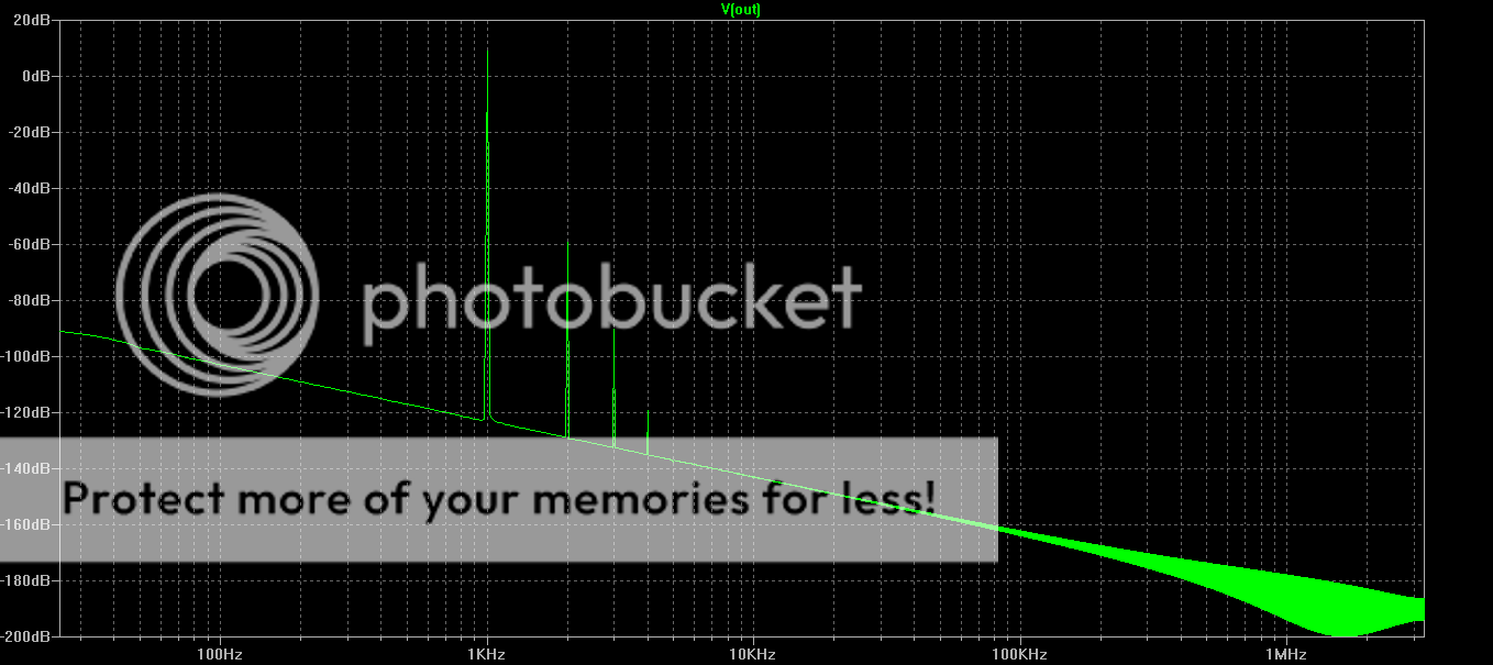
The second has an added cascode to the IXYS hockey puck to reduce capacitance.
Both results are exceptional really. You'd have to build both to judge with your ear.
Really good!
How did you manage the voltage reference...?
These are simulated results, I just added a simple voltage reference so that the circuit biased up at 3Amps
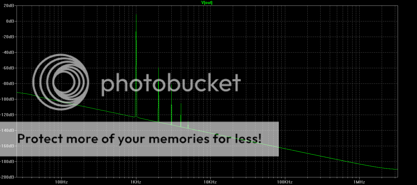
I am using this one from IXYS not exact but SOT227 with similar transconductance and capacitance.
Good enough to get a feel for the amp
.model IXFN90N30 VDMOS(Rg=3 Vto=3.6 Rd=13.2m Rs=9.9m Rb=17m Kp=90 Cgdmax=30n Cgdmin=10n Cgs=100n Cjo=30n Is=720p mfg=IXYS Vds=300 Ron=33m Qg=360n)
Good enough to get a feel for the amp
.model IXFN90N30 VDMOS(Rg=3 Vto=3.6 Rd=13.2m Rs=9.9m Rb=17m Kp=90 Cgdmax=30n Cgdmin=10n Cgs=100n Cjo=30n Is=720p mfg=IXYS Vds=300 Ron=33m Qg=360n)
For the cascode I just used IRFP240, but a low capacitance Cree device as the cascode would turn the Hockey puck into a bloody super device.
I only cascoded the common source device not the follower
I cascode to source pin not to ground (actualy no difference in this case, source is at ground).
I only cascoded the common source device not the follower
I cascode to source pin not to ground (actualy no difference in this case, source is at ground).
Last edited:
Both simulate really nicely into a 4 Ohm load (ie 4Vpk into 4Ohms)
How many Watts into 4 Ohm?
How many Watts into 4 Ohm?
(4^2/4)/2 = 2Watts avg into 4Ohms
I can measure at higher watts.
At 5 Watts avg into 8 Ohms the cascoded version starts looking quite a bit better than stock, but most of what you hear is happening in the first watt, so hard to quantify the real improvement when you think of it from that view point
Last edited:
- Status
- This old topic is closed. If you want to reopen this topic, contact a moderator using the "Report Post" button.
- Home
- Amplifiers
- Pass Labs
- BAF 2015 Coverage