So I had a longer post edited that went into the abiss, due to the site not responding... oh well.
A shorter version of it: Babo, I'm not doubting you're using those parts. You have the upper hand, having built the thing. I was merely trying to point out a little red flag coming from the simulator.
Andrew, as always, I appreciate your suggestions and when I have interest in a project I actually test what you suggest. The zout and line regulation of Babo's design are not exactly stellar yet, hence I'll put for some effort in a different direction. Unfortunately, time give to the hobby is limited, so I have to choose with care. Incidentally, no regulator that I have tried has yet as good a performance as the variation of salas' simplistic shunt that I'm using (low current though). The Toole design came very close but it's plagued by some weird problems still, IMHO. Still looking... and learning")
A shorter version of it: Babo, I'm not doubting you're using those parts. You have the upper hand, having built the thing. I was merely trying to point out a little red flag coming from the simulator.
Andrew, as always, I appreciate your suggestions and when I have interest in a project I actually test what you suggest. The zout and line regulation of Babo's design are not exactly stellar yet, hence I'll put for some effort in a different direction. Unfortunately, time give to the hobby is limited, so I have to choose with care. Incidentally, no regulator that I have tried has yet as good a performance as the variation of salas' simplistic shunt that I'm using (low current though). The Toole design came very close but it's plagued by some weird problems still, IMHO. Still looking... and learning
Well . . .
After installation of this voltage-feedback series regulator into my F5 (incl. removal of the current-limiting circuit part), I have tried various music for about one week.
I conclude that I get real improvement in sound. Among others, improvement in clarity and "particularly in base end definition".
I am satisfied with the result I get
Attachments

Babowana said:Well . . .
After installation of this voltage-feedback series regulator into my F5 (incl. removal of the current-limiting circuit part), I have tried various music for about one week.
I conclude that I get real improvement in sound. Among others, improvement in clarity and "particularly in base end definition".
I am satisfied with the result I get
Thaks Babo for this "feedback" on the sound.
What is most interesting is that you seem to get a better sound with 66000 uf regulated PSU than with 198000 uf unregulated. I suppose it is even a cost reduction to use this voltage regulator compared to the high price of higher cap bank value using low ESR big electrolytics...
can you confirm?Is it Jaco Pastorius on the picture?
Yes, it's true. I can save the initial cost by reducing the total capacitance. However, as I have to burn off few voltage through the pass transistor of the regulator, I have to pay few extra electricity fee monthly. So, in long term . . . I do not know which way is more economical at the end . . .
Yes, he is Jaco Pastorius.
Oh . . . also improved in dynamics . . .
Yes, he is Jaco Pastorius.
Oh . . . also improved in dynamics . . .
Babowana said:Well . . .
After installation of this voltage-feedback series regulator into my F5 (incl. removal of the current-limiting circuit part), I have tried various music for about one week.
I conclude that I get real improvement in sound. Among others, improvement in clarity and "particularly in base end definition".
I am satisfied with the result I get
Babowana said:Yes, it's true. I can save the initial cost by reducing the total capacitance. However, as I have to burn off few voltage through the pass transistor of the regulator, I have to pay few extra electricity fee monthly. So, in long term . . . I do not know which way is more economical at the end . . .
Yes, he is Jaco Pastorius.
Oh . . . also improved in dynamics . . .
Well congratulations Babo! I'm happy that this project worked well for you.
WRT burning a few volts, I'm sure you know that you could replace the MOSFETS
with BJTs and have much less voltage dropout. Another advantage to the BJT
approach is needing less heat sink for the pass transistors.
Yes, I think you're right that less bias current will lead to higher THD measurements.
But I don't know how much more. Maybe it is insignificant. But you might want to
review the Zen 5 article again for some interesting information. With both (relatively)
low voltage and low current, the THD level might be higher than you would expect.
What does seem clear is that you and I listen to music and different sound pressure
levels!
Did you happen to measure the regulated voltage ripple? The maximum vertical
resolution of my scope is 10mV/Div (not very sensitive). With it, I could measure
no ripple on my regulated rails. Yet, I could still see a very small amount of 60Hz
hum at my outputs (I don't remember the magnitude of the 60Hz signal - it was
small, but measurable). How about for you?
Congratulations again!
Robert
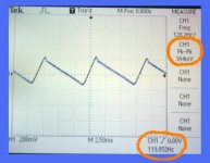
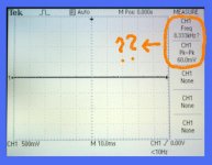
Babowana said:Then, I have also measured at the ouput of the series regulator, and found the pk-pk of about 40mV-60mV. But, I have read frequency . . . strange values only ???
I don't have a Tektronics scope, so I could be misreading the instrument. Is the last
screen shot saying that the vertical sensitivity is set to 500mV/division? If so, you
might want to set that to something like 10mV/div or 1mV/div (something more
sensitive) and see if the signal is still flat. In this case, flat is a good thing! The
non-flat part is your ripple and noise.
The ripple may be less than the resolution of your scope, and the frequency counter
in the scope might not be fed a strong enough signal to give an accurate reading.
If the vertical sensitivity is not enough to show us anything, then you can stop here.
If you can measure some ripple, then you might scan through the sweep rates to
see if you can detect 1 or more frequencies of ripple. If your scope has an FFT
capability, that might help identify the frequencies and magnitudes.
Or have I completely misunderstood your question?
Let me know how I can help,
Robert
I have tried adjusting both V/div (down to 20mV/div) and Sec/div, but could not get any other curve than the flat shown . . .
Could be that my scope has not good enough resolution . . .
I have no idea what to do further . . .
In the rainy dark night, 4AM . . . I can't sleep well . . . . . .
. . .
Could be that my scope has not good enough resolution . . .
I have no idea what to do further . . .
In the rainy dark night, 4AM . . . I can't sleep well . . .
. . .Attachments
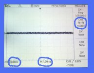
Babowana said:I have tried adjusting both V/div (down to 20mV/div) and Sec/div, but could not get any other curve than the flat shown . . .
It may be the case that the voltage ripple is below the noise floor of your regulator. The scope is likely doing an FFT on the signal and finding no dominant frequency, so the fluctuations in pk-pk and frequency could be just noise.
Have you tried a small value film cap across the output?
-j
Babowana said:I have tried adjusting both V/div (down to 20mV/div) and Sec/div, but could not get any other curve than the flat shown . . .
Could be that my scope has not good enough resolution . . .
I have no idea what to do further . . .
In the rainy dark night, 4AM . . . I can't sleep well . . .
I'm guessing that Sec/div means 1Sec/div. If I'm right, this would be way too
slow. You want a sweep time in the range of the frequency you are trying to
find. If your AC mains are at 60Hz, then you're probably interested in seeing
120Hz. 1/Freq will tell you the time of 1 cycle. 1/120 = .008333s or about 10ms.
If there is 120Hz signal, setting your horizontal sweep time to around 10ms/div
should show you about 1 cycle/div.
You may want to see fewer cycles to be able to focus or see more detail of
1 or a few cycles. You could increase your sweep rate to see higher frequencies
and fewer of the 120Hz cycles. Likewise, you could slow the sweep to see
lower frequencies.
Is this the kind of info you are wanting, or is this stuff you already know?
(I'm trying to learn how to help you.)
Following what Nelson said, you may have probes on your scope that have
a 1X/10X switch, and you are set at 10X. Or maybe you have a 10X probe,
and can buy a 1X probe. You may have a 1X/10X button on the scope too,
to set the right scale. In other words, you may be able to switch to 1X, and
be able to select a vertical sensitivity of 2mV/div (instead of 20mV/div).
Or Diomedian may be right, and you have reached the limit of what your
scope can do. Maybe you could call your Tektronics rep and see what
options are available to you?
I hope that helps,
Robert
Papa, yes, X1 probe get me down to 5mV/div.
Diomedian, yes, I put 1uF film cap across the output.
Robert, yes, it seems that it has reached the limit of what my
scope can do . . .
Thank you, for all . . .
I want to have some nap and have to take one hour walking on a daily routine . . .
Diomedian, yes, I put 1uF film cap across the output.
Robert, yes, it seems that it has reached the limit of what my
scope can do . . .
Thank you, for all . . .
I want to have some nap and have to take one hour walking on a daily routine . . .
Attachments
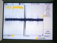
You can pick up a lot of artifacts from sources both within and outside of the power supply. You can see the diode switching transient on the first oscillogram -- you can eliminate it by getting the correct snubber value across the diodes -- a good approximation of the diode's junction capacitance should be in the datasheet. Required reading: http://www.hagtech.com/pdf/snubber.pdf There are also some good articles on eliminating diode or bridge ringing on the On-Semi and CDE websites.
I first saw this on an "Analog Dialogue" article -- if you are measuring tiny voltages you can artifacts from fluorescent lamp light impinging on any PN junction -- if you have a high tech soldering station it can emit RFI as it switches --
Just wait until compact fluorescent bulbs rule the universe.
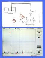
Babowana said:Before I have turned off my oscilloscope . . .
I have tried to measure the Math FFT mode at 1kHz of the amp's ouptput in thr first watt area.
I see neither 2nd harmonics nor 3rd harmonics clearly . . .
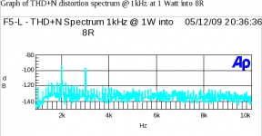
HI Babo,
You may need to notch filter the 1kHz input signal from the output before
measuring, to be able to more clearly see the harmonics. Here is a
graph of my F5 at 1kHz at 1W into 8 ohms. Like you, my F5 is not quite
what Nelson designed (because of what I had, not because I think I can
do a better than Nelson). Note the 1kHz input signal is filtered. Also, I'm
not sure what your vertical scale is, but you should be able to sum the
magnitudes of the harmonics (and other noise) to give the THD+N of your
amp.
Also, you might want to remove your input signal, short your input to ground,
and do your FFT at the output again, to see what is there with no input.
I posted a graph of this for my F5 and 400A in the 400A thread.
Jack - very good info. I'm going to have to read that a couple of times.
Thanks for sharing!
Robert
Attachments
Hi Jack,
Thank you for the very good info.
I will read further about the damping coefficient of 0.5, snubber resistor, role of snubber capacitor and how to calculate them . . .
Hi Robert,
The set of your advice and info is clear and is of great help.
The vertical scale is 10dB/div. Again, my scope seems to be not good enough to cover some of my interests. I will try to remeasure the harmonics using the notch filter as you say. At present, however, I need to save available time and energy . . . So, it might take certain time . . .
The leakage inductance ranges from a bit under 10uH to a hair over 12uH for the Antek transformer I am using. Figure that the junction capacitance of a MUR860 is circa 100pF at 25V. Thus the snubber resistor is around 300 ohms. the capacitor I would use would be 1nF although the calculated value is ~700pF.
FWIW, I put another 10nF in parallel with the RC snubber -- the RC snubber brings down the sharp switching transient and the second lowers the ringing frequency as Hagerman demonstrates. Belt and suspenders. You don't want the second snubber value to be too large else it feeds through more a.c. to the filter caps and overheats them.
Just for jollies I measured SY's Allied Electronics transformer used in the Impasse Preamp -- it measured 178uH -- but the diodes he uses UF4007 have such negligible junction capacitance that the ringing is up around 5 MHz!
Did I mention that the locale for Antek's plant is close to the first copper mine in the US? It was a Dutch settlement on the east side of the Passaic river.
- Status
- This old topic is closed. If you want to reopen this topic, contact a moderator using the "Report Post" button.
- Home
- Amplifiers
- Pass Labs
- Babo Tries New Voltage Regulator for F5