Babowana said:
...No. Look at my old PSU having total 198,000uF. I compared the sound new one with this old one. I prefer new one. And, for your info, I have never tried the one suggested in Papa's documentation....
><
Wow ...!
I think I have figured out that the F5 with your new PSU version sounds better than the one with Papa's suggested PSU...
ikoflexer said:
In simulation this circuit buckles under anything larger than 1.2A for me.
Could you post your schematic and simulation?

Babowana said:
Could you post your schematic and simulation?
It is your own schematic, from post #1; I used the exact parts you have in it. I'm not sure what you mean I should post from the simulation. I can tell you that with a 1.4A load the output voltage ends up in the millivolt range.
ikoflexer said:
It is your own schematic, from post #1; I used the exact parts you have in it. I'm not sure what you mean I should post from the simulation. I can tell you that with a 1.4A load the output voltage ends up in the millivolt range.
I don't know very well about the simulation.
In real world, mine should work fine. 1.4A generate very low voltage across the current-sensing resistors . . . Are you sure you did your simulation correctly?????? I hope you will do double checking before you make my heart buckled . . . I'm weak . . .
Hm... I had a square wave load between 1.4A and 1.45A, which might have been brutal. Changed the load to a sine wave, and now it works up until 2.4A.
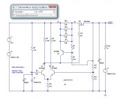
Andrew, the voltage across the two resistors with a 500mA load is 4.26V and 10.51V respectively (Vin = 28V). When the load is high enough for the output voltage to be in the millivolt range the voltage across R5 is almost zero.
Babo, don't worry so much, if it works well enough for you, it should not matter what a simulator says.
Thanks, Juma, for your schematic and simulation!!!!!!!!!!!! I would like to try the added current mirror in the future.
Meanwhile, my current version seems to give me maximum 10A with 2.4ohm load. Then, when the load resistance goes down below this, the load current and the output voltage go down too. Finally, when the load resistance is almost zero (short), the load current goes down to 2A and the output voltage to zero . . .
><
Meanwhile, my current version seems to give me maximum 10A with 2.4ohm load. Then, when the load resistance goes down below this, the load current and the output voltage go down too. Finally, when the load resistance is almost zero (short), the load current goes down to 2A and the output voltage to zero . . .
>
<Attachments
ikoflexer said:
Babo, don't worry so much, if it works well enough for you, it should not matter what a simulator says.
Okay, thanks!
>
<diyAudio webmaster, if you read this . . . why the connection is so instable these days?
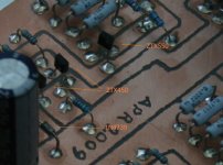
Well, are we comparing apples with oranges here? I'm not sure. Not that I trust simulator that much, but for this simulation I have used 1n4739, ztx450 and ztx550, and an active current load, as opposed to a resistor. Don't mean to be pedantic here, but there's a bit of a difference between ztx450 and bc546b.
Incidentally, if any of you are using the ltspice 9240 model, it behaves quite a bit differently than other 9240 models found on the net.
FWIW, replacing R5 with five 2V forward drop leds does improve the behaviour quite a bit.
Incidentally, if any of you are using the ltspice 9240 model, it behaves quite a bit differently than other 9240 models found on the net.
FWIW, replacing R5 with five 2V forward drop leds does improve the behaviour quite a bit.
if the voltage across R5 is dropping towards zero then that indicates that Q6 is aiming for cutoff.
The LTP cannot compare the two inputs if one side is cutoff.
The LTP must be balanced first and then it will be capable of behaving as a differential amplifier. The range of current in the collectors will determine the range of currents it can send as control signals to the pass transistor.
The LTP cannot compare the two inputs if one side is cutoff.
The LTP must be balanced first and then it will be capable of behaving as a differential amplifier. The range of current in the collectors will determine the range of currents it can send as control signals to the pass transistor.
AndrewT said:
if the voltage across R5 is dropping towards zero then that indicates that Q6 is aiming for cutoff.
The LTP cannot compare the two inputs if one side is cutoff.
The LTP must be balanced first and then it will be capable of behaving as a differential amplifier. The range of current in the collectors will determine the range of currents it can send as control signals to the pass transistor.
Andrew, where is Q6?
Refer to the schematic in post#1 and I hope you will understand the following basic concept clearly:
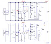
Until the maximum current of 10A through the pass TR is reached, the voltage across R5 is above zero and Q2 is on. But, if the current is going to more than 10A (e.g. due to shorted output), then Q2 is cut off and, instead, Q3 is turned on, pulling the voltage across R4 down and pulling the current flowing through the pass TR down . . .
Regards,
>
<AndrewT said:
On the upper one we have 20mV extra and on the other we have 50mV extra
No special meaning for me.
I would compare the base voltage between 9V of the upper Q2 and 9.04V(with respect to the -rail) of the lower Q2. The difference is 0.04V so that the difference between the +rail and the -rail voltages is by 0.04/11*26=0.1V. So what . . . ???
Regards,
AndrewT said:Hi Babo,
we have already discussed this at length some months ago.
I'm trying to guide Iko through some ideas to try to improve the regulator.
I know you are not willing.
Andrew,
No, we have not discussed any. Mostly, we have been insisting on own. You have called me an obstinate engineer. Probably, it's true I am. I think you are not like me . . . But, you always just talk like an almighty or a big man in one way for everything. Do you believe yourself that you are an authorized forum advicer? No, sorry, but you do not have that quality. Please think about yourself by heart.
Whenever I asked why, how many times did you reply my questions technically with qualified technical background or real experience?
Regards,
I'm tired enough with some of inexperieced clever guys . . .

- Status
- This old topic is closed. If you want to reopen this topic, contact a moderator using the "Report Post" button.
- Home
- Amplifiers
- Pass Labs
- Babo Tries New Voltage Regulator for F5