Looking at the scope shots, the scope wasn't set up to display frequency and voltage, as only "****" was displayed for the values. However it seems that the horizontal scale was 5ms/division. Doing it the old fashion way as in the days of analog scopes, the period of all of the waveforms appeared to be about 8ms, so the frequency was about 120Hz, for both PS output and amplifier output.
The PS rail shots do show the voltage to be 116mV peak to peak.
The scope output voltage was probably 20mV/division. That seems to jive with the 116mV p-p of the PS output. So that gives the amplifier 120Hz output as approximately 30 to 40 mV peak to peak.
The PS rail shots do show the voltage to be 116mV peak to peak.
The scope output voltage was probably 20mV/division. That seems to jive with the 116mV p-p of the PS output. So that gives the amplifier 120Hz output as approximately 30 to 40 mV peak to peak.
Wouldn't the sound going away immediately after turning the amp off suggest that the cap bank supply to the amp is draining immediately?if playing some signal - music, whatever, not loud - for how long you have signal in test speaker, after moment of switching it off?
Back at it here this weekend.
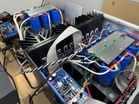
Test 1 - L AMP - Bolted everything up and rolled it over to the other side of the house and hooked it up to the theater/SLOB system, unfortunately no luck, still hums (xfmr and spkr) as before. Made sure no lights, etc. were on throughout house, unfortunately made no difference.
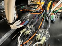
Test 2 - R AMP - Put the Saligny bridges back in and measured for a snubber while things were apart. Hooked up the R AMP bridge output in parallel with the L AMP Cap Bank (R AMP Cap Bank disconnected). Fired up R AMP and speaker/transformer hummed as before. Fired up L AMP and the speaker hum doubled in volume. Transformer hum essentially went away.
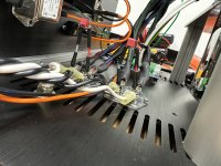
Test 3 - In progress, but will try to rig up a little transformer snubber this afternoon with only one set of bridges connected.
Observation, not sure if it makes sense, but when the FE is connected through the ground wire to the ground plate the Neg Rail of the power supply shows continuity with ground.
Test 1 - L AMP - Bolted everything up and rolled it over to the other side of the house and hooked it up to the theater/SLOB system, unfortunately no luck, still hums (xfmr and spkr) as before. Made sure no lights, etc. were on throughout house, unfortunately made no difference.
Test 2 - R AMP - Put the Saligny bridges back in and measured for a snubber while things were apart. Hooked up the R AMP bridge output in parallel with the L AMP Cap Bank (R AMP Cap Bank disconnected). Fired up R AMP and speaker/transformer hummed as before. Fired up L AMP and the speaker hum doubled in volume. Transformer hum essentially went away.
Test 3 - In progress, but will try to rig up a little transformer snubber this afternoon with only one set of bridges connected.
Observation, not sure if it makes sense, but when the FE is connected through the ground wire to the ground plate the Neg Rail of the power supply shows continuity with ground.
Attachments
Test 2 - ........ Transformer hum essentially went away.
which sez - if snubbers do not help in regular arrangement ( one donut per channel) - donuts are weak for load
Observation, not sure if it makes sense, but when the FE is connected through the ground wire to the ground plate the Neg Rail of the power supply shows continuity with ground.
it does not make sense, at all!!
disconnect said wire from GND, check gnd pad/trace on FE pcb for continuity against neg rail on same pcb
Understood on the donut strength.
With FE board isolated from ground plate and output stages, no continuity between GND and rails on FE board. Maybe false alarm, so I measured vs beep.
With FE board isolated from ground plate and output stages disconnected through ribbon (but rails still connected to OS), continuity beeps between Neg Rail and GND plate (-4.1 MOhm reading??) and Pos Rail to GND plate (1 Mohm).
if FE board isolated from cap bank GND is not showing anything weird ( continuity test) then funny beep you're having with GND connected to FE, - you're trying to top up/or drain capacitors in cap bank
swap black-red probe , and you'll get same effect on opposite rail too .......... either measuring at cap bank itself, or FE connected to OS and cap bank ......
so, false alarm
swap black-red probe , and you'll get same effect on opposite rail too .......... either measuring at cap bank itself, or FE connected to OS and cap bank ......
so, false alarm
ZM running in circles
is there a change in hum in speakers with inputs grounded vs. inputs open?
is there a change in hum speakers with inputs grounded, if you short XLR pin 1 to chassis?
hope you have all elements of chassis, even if dismantled, in some way connected all to safety gnd - if nothing else - with pieces of wire bolted temporarily to each plate/heatsink/bottom

Sorry ZM, wish there was something obvious here!!
1 - Inputs grounded is louder speaker hum than inputs open. 3dB on the high tech iphone dB app. Noticeable to the ear.
2 - No change in speaker hum with pin 1 grounded to chassis. Other inputs open.
3 - Yes this is all on the amp that is all bolted up with all sides on at this point, only missing top cover.
Hi,
I'm newbie here and follow this post as I built something remotely similar in the past.
Might be i missed something, did you post complete wiring diagram somewhere?
Another question; is it typical mains introduced buzz(50-60hz - 100-120hz buzzzzzz) or electronic noise (hummmmmm) here is written about both, not sure what's problem?
Normally fully balanced things shouldn't suffer hardly from ground buzzz. However in original circuit I see few things in DC servo connected to "ground", where that "ground" goes?
Cheers,
Drazen
Welcome to the forumsI'm newbie here and follow this post as I built something remotely similar in the past.
") If you feel like it, it would be cool to see some pictures of your project!
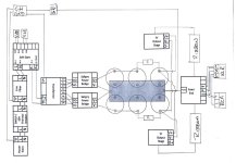
If you feel like it, it would be cool to see some pictures of your project!Took a breather for a while and set this aside. Plugged them back in today and no miracles have transpired in the past couple weeks. We are still buzzing. Drazen - Took your advice and drew out the wiring, attached. Nothing jumped out at me, but open to critiques and recommendations as always.
We are still buzzing. Drazen - Took your advice and drew out the wiring, attached. Nothing jumped out at me, but open to critiques and recommendations as always.Attachments
- Home
- Amplifiers
- Pass Labs
- Babelfish XJ , or JX …….. or whatever (Aleph X servo for Greedy Boyz)