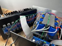
Hi all - wanted to summarize my current power supply components and see if there are any recommendations for areas to change:
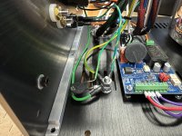
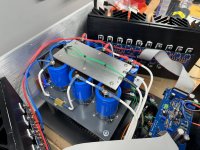
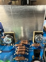
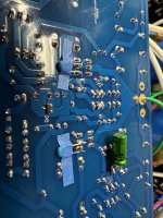
IEC -> 10A Thermal Breaker/Switch TA45-ABDBL100C0 -> 6A Line Filter 5500.2652.04 -> Neurochrome Intelligent Soft Start -> Toroidy 1200VA, 117VAC Primary, 4x17.5V secondaries -> SALIGNY® Power rectifiers -> Caps: CDE DCMC643M063CF2F in a CCRC configuration. Caps rated at 12.1 mOhms ESR and 15.5A Ripple Current -> Resistor Dale RH-25 0.1R.
Audio/Circuit to Chassis Grounding is through a CL60.
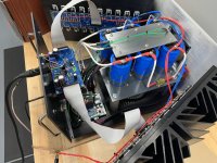
Few more pictures attached of where we stand now.
IEC -> 10A Thermal Breaker/Switch TA45-ABDBL100C0 -> 6A Line Filter 5500.2652.04 -> Neurochrome Intelligent Soft Start -> Toroidy 1200VA, 117VAC Primary, 4x17.5V secondaries -> SALIGNY® Power rectifiers -> Caps: CDE DCMC643M063CF2F in a CCRC configuration. Caps rated at 12.1 mOhms ESR and 15.5A Ripple Current -> Resistor Dale RH-25 0.1R.
Audio/Circuit to Chassis Grounding is through a CL60.
Few more pictures attached of where we stand now.
Attachments
just for giggles, to be sure that servo circuit is absolutely stable, temporary increase value of C12
take another 10uF to 22uF/16V and solder across C12 leads
practically - one pin to Q15 base, second pin to GND
if everything is OK with servo, there will not be change in hum
take another 10uF to 22uF/16V and solder across C12 leads
practically - one pin to Q15 base, second pin to GND
if everything is OK with servo, there will not be change in hum
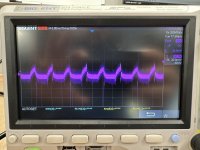
OK Not a Scope expert, but here goes:
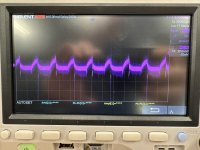
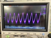
Left Amp, Inputs Shorted, Speaker Load Connected, Still in CRCC, Scope AC Coupled, GND taken from 'clean' point on plate.
Filenames hopefully explain the measurement.
Left Amp, Inputs Shorted, Speaker Load Connected, Still in CRCC, Scope AC Coupled, GND taken from 'clean' point on plate.
Filenames hopefully explain the measurement.
Attachments


ok, to remove even slightest possibility of circuit oscillation, please do this:
find a pair (per channel) of small caps - anything from 220pF to 1nF will do, either smd 1206 or small ones with pins
solder them on copper side in between C and E pins (or on traces, closest possible to transistor itself) of Q3 and Q12
those being emiter followers, practically final drive to OS
transistor numbers ref. to schm in post #4
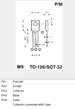
that being pins 1 and 2, pins down, label to you
find a pair (per channel) of small caps - anything from 220pF to 1nF will do, either smd 1206 or small ones with pins
solder them on copper side in between C and E pins (or on traces, closest possible to transistor itself) of Q3 and Q12
those being emiter followers, practically final drive to OS
transistor numbers ref. to schm in post #4
that being pins 1 and 2, pins down, label to you
Attachments
oh man
is there a way to - temporary - connect two Donuts, together with their bridges, to one cap bank?
practically - disconnect wires going from one channel bridges to cap bank, and connect to other channel cap bank?
that way having two xformers feeding one cap bank, bridges are there so paralleling is proper, and each xformer dealing with just half load
I mean, I exhausted ideas - everything regarding amp circuit, even if least likely to be a problem, we tried ........ wiring arrangements - logical and less logical, bridges....
now I can only think of snubbers for xformer secondaries, but that's just hanging on the straw
@04dgmsilv - I haven't read all the efforts you've made yet or your exact symptoms, but have you ruled out mains issues?
As an example, I've witnessed recently that dimmable LEDs can mess things up quite nicely. I had a nasty situation of my own with a florescent ballast.
May apply... may not... Hope you get it solved. Hum chasing is not my favorite thing.
As an example, I've witnessed recently that dimmable LEDs can mess things up quite nicely. I had a nasty situation of my own with a florescent ballast.
May apply... may not... Hope you get it solved. Hum chasing is not my favorite thing.
Thanks ZM - I imagine I can wire that up next weekend.
ItsAllInMyHead - The garage circuit does have non-dimming LED lights, battery chargers, etc., so last weekend I did run an extension cord to the laundry room GFCI that is on it's own breaker with nothing else plugged in and unfortunately no difference.
ItsAllInMyHead - The garage circuit does have non-dimming LED lights, battery chargers, etc., so last weekend I did run an extension cord to the laundry room GFCI that is on it's own breaker with nothing else plugged in and unfortunately no difference.
In my friend's situation with the LEDs, they were on a completely separate breaker also. He found it by shutting off various breakers until the toroid quit humming. He moved the amp to a different room, different breaker... hummm..... LEDs out of the picture. Blissfully quiet.Thanks ZM - I imagine I can wire that up next weekend.
ItsAllInMyHead - The garage circuit does have non-dimming LED lights, battery chargers, etc., so last weekend I did run an extension cord to the laundry room GFCI that is on it's own breaker with nothing else plugged in and unfortunately no difference.
Give it a whirl ... if you care to... and just turn them off / shut that breaker off (if it's not too much effort.)
I'm not in any way saying that it's definitely your situation, but ... at this point... it may be worth a shot.
It’s curious why
all 4 scope readings are pretty much equally dirty, so I reckon (with everything else taken in account) that's due to measurement itself - see just how long that wire to central GND point is
anyhow, sound file posted before clearly shows 120Hz as main ingredient; yup, it was weak in volume, so to be sure I needed to pull it in Sound Forge and do some tweakering, but then it was conclusion
- Home
- Amplifiers
- Pass Labs
- Babelfish XJ , or JX …….. or whatever (Aleph X servo for Greedy Boyz)