choky said:
laser printer
Yes, I have.
But, I might require number of pieces more than one . . .
I drawn the drawing manually, not using any program.
Still any pro shop could produce it to order?
Ah, the printer . . . Next step?
(Sorry for the thread-jack.)

choky said:
pissssssss off ya old fart!
ya can tell me "bad photos" !
I can't take few with Canon,just because I don't have photo lab in basement........
hehe-I'll take not just one bear next weekend

Stop drink beer...save money...bay Canon...make not blurrrred

Nice boards, Choky. Looking forward to hear about how they sound.last blur
Steen
")
jh6you said:
Yes, I have.
But, I might require number of pieces more than one . . .
I drawn the drawing manually, not using any program.
Still any pro shop could produce it to order?
Ah, the printer . . . Next step?
(Sorry for the thread-jack.)
pro shop ?
depending of that -how much they are pro...ya know-"customer must be pleased" rule....
try to google for "toner transfer pcb"
I'll try to find saved pages in few PCs of mine,and than I'll give you URL
vangelis said:
Stop drink beer...save money...bay Canon...make not blurrrred
I already have Canon
you

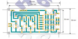
there it is -schematic -working version ;
pretty stable,without any pop or plop during powering up or shutting down;
DC offset -typical for so simple schematics -starting from cold with less than 200 mVdc,and then decreasing to o Volts ,and staying there;
didn't checked anything with CRO,but-who cares
PS is twice 25V ,Iq 2A (~4V4 on gates of output mosfets)
sound : very nice!
I have not opportunity in this moment to compare it with Babelfish Aleph J,but -from memory -Babelfish is somewhat more authoritative ;
I expect some logical differences when I make both of them in final boxes etc - Oly's Mini is strictly symmetric and Babelfish J is (still ,hehe) SE........ya know all that stuff about even and odd harmonics........
anyway- who cares-it sings!
Oly is magician with PCBs ,and I must admit - he study very well work of his favorite Audio Grand Pa Borbely
ps. this little amp is somewhat leaned on some Frenchy amps ,but i think that must be more stable than ,say,Profet or similar one
Attachments
I am happy to say that I dosteen-you have some news for me?
With the help of some of the very kind and nice persons here on the board I found some of those J-fets.They are not in my hand yet, but they are payed for and on their way
Steen
jfets for project?
Hello all,
After converting my Aleph 3 to the babelfish version, I am frustrated. Maybe I have some trouble shooting you could help with.
I converted my Aleph 3 to this babelfish version using the j176 jfets.
Does anyone know are the j176 better or worse than the 2sj109's?
I noticed the data sheets show the j176 has lower capacitance, so in theory should be better for high frequency?
The j176 sounded nice, but I noticed my previous zvp3310a Aleph 3 version with the standard zener regulator, seemed to sound like the upper frequencies were better than this j176. I checked the AC current gain and made sure the DC offset with the j176 was below 100mV. Could I change the 33.1K ohm value to say 25 or 26K ohm? Would that help for the current source?
It seemed like my zvp3310a directly substituted in place of the irf9610 sounded better or more sweeter compared to my j176.
Why would this be? I went with this j176 hoping I could bias it close to 20 mA for the current source and not need to parallel any jfets. This did work fine. It handled the power, but still did not sound as musical as my zvp3310a. I am running the output mosfet very hard, because the bias resister to the outputs was removed biasing the mpsa18s as hard as they will drive.
Has anyone else tried any other jfets other than the 2sj109?
Why would the zvp3310a with 50 pF sound better in the upper frequencies than this j176 with 8 or 30 pF?
I thought zeners were supposed to be noisy and thought the resister current source should be cleaner sounding than a zener. Maybe because the resister current source does not regulate as well as a Zener could be the problem?
Other observations:
I have also noticed the Zener regulator stabilizes much faster in a couple of seconds, compared to this resister current source, which takes up to a minute or longer to go below 100mV. Sometimes when it was first running it took 5 to 6 minutes to stabilize below 100 mV.
Also the jfets are very sensitive to air currents. I ended up using a heatsink for the j176 to keep the current source jfet from drifting too much. The differential LTP were not as sensitive to drift compared to the j176 current jfet.
It took about 5 or 6 hours of adjusting the circuit and moving fans away from the jfet to solve the dc offset drifting problem.
I used a 1Kohm pot instead of the 47 ohm resister with 47 ohm pot. Could that be the problem if this 1Kohm pot was in place of the 47 ohm and 47 ohm pot?
Do I still need a 1Kohm resister after the j176 current source between the LTP as in the choky schematic? Could that be the problem or is simply the j176 not as musical as my zvp3310a?
Regards, Bill
Re: jfets for project?
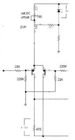
Recently, I got better confidence with the zener reference with the mosfet follower. For example, I am playing like this (my first try with PCB), for the fun now . . .
BillWW said:
I thought zeners were supposed to be noisy and thought the resister current source should be cleaner sounding than a zener.
Recently, I got better confidence with the zener reference with the mosfet follower. For example, I am playing like this (my first try with PCB), for the fun now . . .
Attachments
BillWW:
First thing-you must post drawing of your input stage to make clear to me what you wrote;
I understand that you use 2 x 2SJ176 in LTP
but-I do not understand how you make CCS for LTP - as in mine Babelfish or as in Aleph ,but with 2SJ176 instead of IRF ?
in any case,you mentioned 33K,so I still resume that you made CCS with two bjts....
in that case-changing 33K to lower may help but just a little,because temperature drift,at least for my knowledge ,is not problem here for CCS but for LTP himself.
CCS have pretty good tempco,if you couple these two bjts thermally (face to face with some white goo
also-because you use two solo Jfets in LTP,they also must be coupled.
difference in highs between zvp and jfet version must be from LTP drive (un)capability of output mosfet's capacity;
like you can see-NP uses in Aleph J two pairs of output mosfets,same as in A3
I use just one pair of IRFP150N,strictly from input capacitance issues
just one thing-from top of my head-J176 isn't intended for audio applications? choppers etc is primary use for it....
anyway-why you don't use same CCS for LTP as in your zvp version and just set needed current through LTP ? in that case you'll hear exact difference in LTPs,not CCSs....
1K2 on top of LTP is just to decrease power dissipation in CCS,nothing else-you can try without it
also-using 1K pot instead 47 will give you more drift in resistance during warming up
just one addendum-I didn't make any "usual" or "common" Aleph before,neither I have opportunity to hear one,so I can make my conclusions just from my Babelfish
I also have no clue how far is from NP's Aleph J
intentionally I didn't say "close"
I still see some drawbacks in Babelfish,but .....
choky said:BillWW:
I do not understand how you make CCS for LTP - as in mine Babelfish or as in Aleph ,but with 2SJ176 instead of IRF ?
I believe I closely made it more like your babelfish.
Is the 2sj176 the same as j176? I could not find any data sheets on the 2sj176. I bought the j176 from www.allelectronics.com that was previously posted in another thread. I purchased a 100 of them and matched them.
I thought you just paralled two smaller p channel fets for your babelfish current source. Maybe this is my problem? Do I need two or just 1 j176 for the current source?
For my current source, I used just 1 j176 instead of two p channel fets for the current source in your schematic, since the j176 was more powerful than the other ones in your circuit, so there should not be any drift in this 1 current j176 source.
I noticed while it was driving the j176 LTP that the DC offset drifted quite a bit while warming up. Perhaps it is because of my larger 1000 ohm resistance like you mentioned previously.
Do I need the 1000 ohm resister between your current source and LTP? I can see I did not follow this part of you circuit, because I would havd had to cut the trace between the current source and LTP to insert it there. Instead, I just added the 1000 ohm pot in place of the 47 ohm and 47 ohm pot.
I rebuilt my Aleph 3 to your ciruit very similar. I do not know how to draw what I did to your circuit or how to insert a photo.
I would like to make a zvp3310a version with resister current source to do a more fair comparison.
When I at first tried this with all three zvp3310a and or irf9610 in place of the j176, the amplifier became very unstable. I received full voltage or about 25 or 26 volts out to the speakers terminals, while the output mosfets did heat up like they were still being driven by the LTP. In one of the LTP, it heated up very hot compared to the other LTP. So, I did not let it run very long, because it would have destroyed one side of the LTP from heat.
But when I leave the j176 in it works fine. So, it seems like I can not try a direct replacement for these other mosfets.
Does it sound like my current source is okay using one j176?
Maybe the j176 is a chopper like you said and it is not as musical as the zvp3310a?
Regards, Bill
Choky,
Should I try an irf9610 or zvp3310a for the current source to see if my j176 current source does not have enough drive current?
Thanks!
When I first experimented with the j176, I just placed it in the stock current source of the original Aleph 3 schematic. It worked fine.
The next experiment, I tried placing a matched pair of j176 in the LTP and that did not work okay. The output heatsinks did warm up to their normal operating temperature, but I found the speaker terminals DC offset was 25 or 26 volts.
Why would that be the case?
This was my stock Aleph 3 circuit.
How could I try the j176 jfet in the stock aleph schematic for a comparison with my zvp3310a or vica versa try the zvp3310a in the babel fish? I have not been able to get this comparison to work directly.
Regards, Bill
Bill- you really need to re-read NP's manuals (service) for Aleph 3-just to figure out which part do what ;
'xcuse me if I take you wrong,but I think that you were pretty lucky 'till now to not burn anything....
if you look closely on Babelfish schematic,you can see that I use two BJTs in CCS; you can't put there zvp or J176 ;
what you can is just on little schmtc attached to this post; it's easiest and fastest way to try J176 Jfets in any Aleph iteration.
besides-game with zvp ....you don't need to change anything in CCS ,just leave old good IRF;CCS is CCS,and few needed qualities are stability and lack of noise ; I have doubts that zvp works better than IRF there,and especially J176-even with proper CCS adjusting
you must alter 390 Ohms resistor in leg of first LTP fet to some 470 ohms,just to decrease dissipation in that little JFet critter....
try it like these,and then write what you hear
besides-as you can see in attachements in next few posts (one attach/post) is that J176 and 2SJ176 are entirely different animals...
try this ,then come again with questions
Attachments
- Status
- This old topic is closed. If you want to reopen this topic, contact a moderator using the "Report Post" button.
- Home
- Amplifiers
- Pass Labs
- Babbelfish J PCBs