I've tested the drops on R10 and R11 before and they're stable at 1V until I put a signal on the input, then they go wacky. I can't re-test them right now as I've taken the board out of the preamp for inspection.
By wacky I mean the bias on one goes high and the other goes low.
When you put it back together use ACV mode on the DMM to see if they are all close when running a non squashed or clipped sinewave through the preamp.
Also when the scope is on AC input mode check that the rails appear as flat and clean enough line without hash or riding frequencies when set for 10mV 1us-100ns sweep.
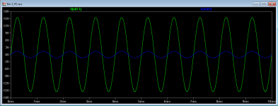
With no input signal and probes on R10 and R11 they stabilize at ~1V. When I put a signal on the input (1V 1K sine wave) the bias on Q3 raises to 1.5V and Q4 drops to .5V.
Yes they are close.
You kinda lost me there. I only understand basic things about the scope.
When you put it back together use ACV mode on the DMM to see if they are all close when running a non squashed or clipped sinewave through the preamp.
Yes they are close.
when the scope is on AC input mode check that the rails appear as flat and clean enough line without hash or riding frequencies when set for 10mV 1us-100ns sweep.
You kinda lost me there. I only understand basic things about the scope.
From your measurements your voltage gain does look to low. The jfets are should have a voltage gain of one and the mosfets a voltage gain of 15 for a tolal gain of 15 or 23.5db. The gain of the mosfets should be 332/22 = 15. With a 1vp-p input signal it should have a 15vp-p output signal. With a 1.5vp-p input it should have a 22.5vp-p output signal.
Could the problem be your input signal? Maybe it has a dc voltage offset.
Could the problem be your input signal? Maybe it has a dc voltage offset.
Of course.Would a dc bias on the input signal cause this problem?
And that is why I always recommend a DC detect for any DC coupled amplifiers.
The least would be to activate a warning LED, but could go as far as shutting down the system on excess DC.
Operator error!
That's it! The signal generator can admix a DC component to the signal. I figured that out last night. I have a meter that reads AC and DC simaltaneosly which was on the input, then I finally read the manual for the oscilloscope/signal generator. If I zero the DC offset on the input everything stabilizes.
For 1V input I get 11 on the output ~21dB.
The bias on the MOSFETs does increase 200mV at full power, is that normal.
Sorry to put everyone through that yesterday.
Thanks for all your help!
Could the problem be your input signal? Maybe it has a dc voltage offset.
That's it! The signal generator can admix a DC component to the signal. I figured that out last night. I have a meter that reads AC and DC simaltaneosly which was on the input, then I finally read the manual for the oscilloscope/signal generator. If I zero the DC offset on the input everything stabilizes.
For 1V input I get 11 on the output ~21dB.
The bias on the MOSFETs does increase 200mV at full power, is that normal.
Sorry to put everyone through that yesterday.
Thanks for all your help!
Last edited:
Pass DIY Addict
Joined 2000
Paid Member


That's it! The signal generator can admix a DC component to the signal. I figured that out last night. I have a meter that reads AC and DC simaltaneosly which was on the input, then I finally read the manual for the oscilloscope/signal generator. If I zero the DC offset on the input everything stabilizes.
For 1V input I get 11 on the output ~21dB.
The bias on the MOSFETs does increase 200mV at full power, is that normal.
Sorry to put everyone through that yesterday.
Thanks for all your help!
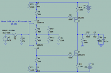
I made a quick simulation out of curiosity for the gain spec question thing and its indeed 21dB for R13=330R even if I used 12mA idss JFET models and IR Mosfets that I had handy in my models library.
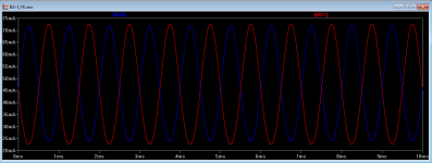
The Mosfets currents should become a little asymmetrical depending on the offset I guess. Here is how they go for mA swing on 1VRMS input and +73mV steady state offset simulation. On +/-24V PSUs. Bias current and its dynamic swing through Q3 Q4 can be translated across R10 & R11 as voltage drops of course.
Attachments
I made sort of translation (in comments area) of original Papa's article , just because Papa made partial mess with nomenclature in sch. vs. txt (certainly urged to entertain always Greedy Boyz) ........ and later (somewhere in original thread) I made comment about sim-ed and measured gain of circuit , being approx. half of what Papa wrote in article
anyway - I'm lazy to search for it ........ even for files in my PC
in fact , they're in other PC , and I'll forget to search for them tomorrow ....
anyway - I'm lazy to search for it ........ even for files in my PC
in fact , they're in other PC , and I'll forget to search for them tomorrow ....
For 1V input I get 11 on the output ~21dB.
The bias on the MOSFETs does increase 200mV at full power, is that normal.
Sorry to put everyone through that yesterday.
Thanks for all your help!
Great! I am sure you are relieved. Are you using all stock values as per schematic for the BA3FE?
nash
Great! I am sure you are relieved. Are you using all stock values as per schematic for the BA3FE?
nash
Yes, I'm using the stock values.
No worries, glad you got it figured out. Iam pretty sure the bias increase is normal but somebody who knows better will chime in.
There was some discussion about the lack of gain with the ba3 a while back. Yours sounds about right. I too thought it didn't have as much as advertised...but it wasn't that big a deal for me with the f5. Actually, I feel like it's just about right, gain-wise. Obviously the solution for the f4 would be another ba3 front end in the same case with the f4...it would basically be the push pull burning amp then. Or get another ba3 board and go balanced in the preamp and get 50 watts from an f4. But Iam sure you will just enjoy what you got for now.
There was some discussion about the lack of gain with the ba3 a while back. Yours sounds about right. I too thought it didn't have as much as advertised...but it wasn't that big a deal for me with the f5. Actually, I feel like it's just about right, gain-wise. Obviously the solution for the f4 would be another ba3 front end in the same case with the f4...it would basically be the push pull burning amp then. Or get another ba3 board and go balanced in the preamp and get 50 watts from an f4. But Iam sure you will just enjoy what you got for now.
Based on my simulation, to have 30dB involves R13=1K and 35V supplies for 2Vpp max input after the pot i.e. 0.7V RMS real input just before clip. Make that 0.64V RMS or 1.8Vpp before the THD turns nasty for high harmonics anyway.
The dissipation on say 8mA biased JFET reaches 240mW while they have 30V across each. I.e. red line PJFET VDS and TO-92 mini-sinks territory. Long term JFET reliability comes in question. A worry for rare NOS matched devices.
The outputs dissipate 1.7W each. Heat goes higher up in all those semis when driven. Means double the heatsinks size than now to cope. You would not like the 9dB extra noise boost in the middle of the gain chain too. All in all better avoid temptation for such a gain mode IMHO.
But Iam sure you will just enjoy what you got for now.
Yes! I am enjoying what a have. It was a preamp shoot-out at my house tonight.

Based on my simulation, to have 30dB involves R13=1K and 35V supplies for 2Vpp max input after the pot i.e. 0.7V RMS real input just before clip. Make that 0.64V RMS or 1.8Vpp before the THD turns nasty for high harmonics anyway.
The dissipation on say 8mA biased JFET reaches 240mW while they have 30V across each. I.e. red line PJFET VDS and TO-92 mini-sinks territory. Long term JFET reliability comes in question. A worry for rare NOS matched devices.
The outputs dissipate 1.7W each. Heat goes higher up in all those semis when driven. Means double the heatsinks size than now to cope. You would not like the 9dB extra noise boost in the middle of the gain chain too. All in all better avoid temptation for such a gain mode IMHO.
Thanks for sharing. That's cool! No, I don't see myself hot rodding a BA-3FE any time soon.
Yes! I am enjoying what a have. It was a preamp shoot-out at my house tonight.
View attachment 528913
Thanks for sharing. That's cool! No, I don't see myself hot rodding a BA-3FE any time soon.
And the verdict of the shootout is? Also, p3 has a pretty dramatic effect as you will figure out, really changes the depth and width if you play with it. It took me a while to get it where I wanted it.
Based on my simulation, to have 30dB involves R13=1K and 35V supplies for 2Vpp max input after the pot i.e. 0.7V RMS real input just before clip. Make that 0.64V RMS or 1.8Vpp before the THD turns nasty for high harmonics anyway.
The dissipation on say 8mA biased JFET reaches 240mW while they have 30V across each. I.e. red line PJFET VDS and TO-92 mini-sinks territory. Long term JFET reliability comes in question. A worry for rare NOS matched devices.
The outputs dissipate 1.7W each. Heat goes higher up in all those semis when driven. Means double the heatsinks size than now to cope. You would not like the 9dB extra noise boost in the middle of the gain chain too. All in all better avoid temptation for such a gain mode IMHO.
Thanks for sharing Salas. Waiting for the BiB boards to arrive before I build my BA3FE.
Like many others I am planning on a lower gain version than the stock which your simulation shows to be around 21db.. Would you be kind enough to plug into your simulation 24V rails, R6, R7 56R and R5 220R. All other values same as in stock schematic. What is your simulated gain?
Thanks. Nash
And the verdict of the shootout is? Also, p3 has a pretty dramatic effect as you will figure out, really changes the depth and width if you play with it. It took me a while to get it where I wanted it.
I had a hard time telling them apart at first. I'm starting to get a handle on their differences. I think they are both pretty neutral, really letting the cartridge and Pearl II shine through. I think the Joule is a little more sweet, the BA-3FE a little more transparent. Of course my bias leans towards the one I built. Although I've really enjoyed the Joule preamp, I'll be showing it the way to the door (helping to fund new projects).
Yes, looking forward to seeing how P3 affects the sound. I guess I would start with 1 turn on the 25 turn pot (which is centered now), but in which direction do you think I should start?
Thanks for sharing Salas. Waiting for the BiB boards to arrive before I build my BA3FE.
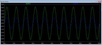
Like many others I am planning on a lower gain version than the stock which your simulation shows to be around 21db.. Would you be kind enough to plug into your simulation 24V rails, R6, R7 56R and R5 220R. All other values same as in stock schematic. What is your simulated gain?
Thanks. Nash
9.45dB if I got you right
Attachments
- Home
- Amplifiers
- Pass Labs
- BA-3 As Preamp