Hi all, I'm working on the ba-3 front end and have a biasing/setup question.
Everything appears normal, adjusting p1 and p2 change voltage across r10 and r11 and I can get those values matched with careful screwdrivering. My issue is that I cannot measure any voltage at all across r12. Even measuring in tenths of mVs, I get zero dc on the offset. Any ideas about what might be amiss?
Thanks as always.
Please note that the PCB for each channel has only three N and three P channel mosfets
(unlike the original schematics, which has six of each). I would go with 0.47 ohm
source resistors (basically like the F4 without the front end jfets).
Thanks for the advice! I was thinking the same thing. But I just ordered the last bits from Mouser. Left out the 0,47 ohms for source, but how about using the specced 1 ohms to begin with, and see how that goes? Reducing source resistance when everything works, could be a cool test. Also, I have an identical spare PSU for the same purpose: when everything works and I it has been going stable for a while, I might det it up as dual mono.
Thanks a bunch for the advice!
Hi all, I'm working on the ba-3 front end and have a biasing/setup question.
Everything appears normal, adjusting p1 and p2 change voltage across r10 and r11 and I can get those values matched with careful screwdrivering. My issue is that I cannot measure any voltage at all across r12. Even measuring in tenths of mVs, I get zero dc on the offset. Any ideas about what might be amiss?
Thanks as always.
I looked at the ba-3 as pre-amp thread and saw alternative instructions to test offset between r12 and ground. That worked for me...
to cal3713 #344
Hello cal3713,
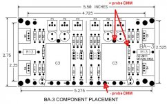
if you want to measure your offset (while adjusting P1 / P2), then put + probe of DMM at R12 or C3 (inputside!) and black probe to G (ground) on BA-3 FE-pcb.
Check pic.
Greets
Dirk
p.s.. You don't measure the voltage over R12
Hello cal3713,
if you want to measure your offset (while adjusting P1 / P2), then put + probe of DMM at R12 or C3 (inputside!) and black probe to G (ground) on BA-3 FE-pcb.
Check pic.
Greets
Dirk
p.s.. You don't measure the voltage over R12
Attachments
So, I finally finished my BOM and ordered all FE and output bord parts. I’ll soon have all the tools I need too. So a long planning process is coming to and end, and hopefully I’lll get to soldering soon.
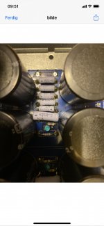
Or de-soldering, for that matter. This picture is from the PSU. I originally bought a failed F5T project, but it will now become a BA-3. as you can see, some strange choices have been made. Notice the extra big 0,47R resistors touching the caps. Also notice the bleeder resistors are of the none fireproof type, as far as I can tell. And the soldering work is not very successful IMO.
Makes me wonder if the PSU at some point was the reason for my predecessors failed project.
So I decided to redo the PSU, leaving only the caps. Those were installed by someone more competent than the original project owners. Only question now is, will I be able to do it better?
I hope so.
Still not decided whether to remove the caps IOT clean up the mess on the PCB. Guess I might have to.
Attachments
A small update: Most of the needed parts have arrived. Output board resistors and diodes are done, and working on PSU. Decided to go for 8x22k caps. BTW source resistors are reduced to 0,47R, as recommended by Nelson Pass in the BA-2 article.
So an important question (I have PMed it to Zen Mod too, but might be of general interest):
I have two pairs of JFETs. Apprently Toshiba 120/70s. But I have no information on whether they are matched or not, where they come from, not even if they are originals. I dont even know if they work, but can of course check them. They look kinda hammered though, probably soldered in and out a few times. I have reason to believe the circuit they were used in, failed tremendously. Unknown if anything blew up. The «Toshibas» look original enough, but like I said, I can’t know for sure.
I have a matched quad set from Linear on the way from the store. In my project, I need to know that the parts I use, work. I want to avoid avoidable troubles, such as parts of unknown origin, or too much experimenting. Thats why I ordered them.
So: should I test the Toshibas, and use them if they work, or play it safe and use the Linears for now? If so, I will save the «Toshibas» for future projects. Perhaps then I can take the risk in using them, and have the knowledge to test then properly. Or is there no or little risk?
Regards,
Andreas
Hi,
Does the Complimentary bias PCB need to be as near as possible from the Complimentary board or can it be deported (around 10-15cm) with tiny wires ? (the output will be taken on the Complimentary board and not on the bias bord...)
Damien
Since nobody has answered, I’ll give it a go:
Ideally, the answer is probably «as close as possible». But, the voltage/current from bias board to output board, is higher than that of the signal wires. And they go a long way, from preamp to input to front end. And how long are they? Probably more than an inch. A «stronger» signal means wire length is less important, and the risk of RFI/EMI affecting the signal significantly, lower.
I assume you ask because it for some reason is difficult or not possible for you to do it the 6L6 way. So do it your way!
If you are paranoid, twist the pair going from bias board to output board.
That’s my take on it, anyway. And excuse the non techincal terms.
Regards,
Andreas
I did mine the same way as 6l6 did in the build thread, where the bias board piggy backs on the end of the OS boards. Short down wires connect. Maybe I'm not seeing the fit problem you are having...but piggy backed they take up no more room, unless the added height of the bias board on top of the OS board makes it interfere with something else?
I wouldn't think short wires would be a big problem if this wouldn't work. I saw an F5 turbo build where the builder had 6 to 8 inch wires going from the amp board to the mosfets, with source resistor on mosfet. I thought it might be a problem but it seemed to operate fine...
As long as proper bias is arriving where it needs to be, I don't see a problem...but wait for wiser folks to speak, I may not be taking something into account that may be very important. It is a burning amp, but I'm sure you want a nice amp (which the BA3 most certainly is) and not a fireworks show.
That said, there is something interesting about the fireworks show, they are just expensive. I hated, that smell of too hot electric train set smell as a child...Now it followed me to this hobby!
Russellc
Thanks Andynor for answering me.
I will put my BA-3 in a smaller chassis and it will be hard to keep original bias board orientation. BA-3 will be a power amp and I will use IronPre before it.
That's why I'm asking.
Damien
Oh, the BA3 sounds GREAT with the Iron Pre!
Russellc
Thanks for the advice! I was thinking the same thing. But I just ordered the last bits from Mouser. Left out the 0,47 ohms for source, but how about using the specced 1 ohms to begin with, and see how that goes? Reducing source resistance when everything works, could be a cool test. Also, I have an identical spare PSU for the same purpose: when everything works and I it has been going stable for a while, I might det it up as dual mono.
Thanks a bunch for the advice!
I built with 1 ohm, the amp is wonderful. I would like to change to .47, but I just always hate "working on" an amp that works perfectly. If I were building it today, I would likely use .47 and closely match the mosfets. I doubt there is much improvement with .47 over 1 ohm, maybe. 1 ohm ought to give more protection from current hogging between output devices I suppose?
Russellc
Last edited:
Preamps for BA-3
On that note, I ask: What preamp should my soon to be beautiful BA-3 be paired with?
What is good about the IronPre?
What about B1 buffer, or B1 Nutube? Or BA-3 preamp?
Oh, the BA3 sounds GREAT with the Iron Pre!
Russellc
On that note, I ask: What preamp should my soon to be beautiful BA-3 be paired with?
What is good about the IronPre?
What about B1 buffer, or B1 Nutube? Or BA-3 preamp?
I did mine the same way as 6l6 did in the build thread, where the bias board piggy backs on the end of the OS boards. Short down wires connect. Maybe I'm not seeing the fit problem you are having...but piggy backed they take up no more room, unless the added height of the bias board on top of the OS board makes it interfere with something else?
I wouldn't think short wires would be a big problem if this wouldn't work. I saw an F5 turbo build where the builder had 6 to 8 inch wires going from the amp board to the mosfets, with source resistor on mosfet. I thought it might be a problem but it seemed to operate fine...
As long as proper bias is arriving where it needs to be, I don't see a problem...but wait for wiser folks to speak, I may not be taking something into account that may be very important. It is a burning amp, but I'm sure you want a nice amp (which the BA3 most certainly is) and not a fireworks show.
That said, there is something interesting about the fireworks show, they are just expensive. I hated, that smell of too hot electric train set smell as a child...Now it followed me to this hobby!
Russellc
I believe I even saw a Nelson amp with MOSFETs cabled to the output stage. Then again, my memory might not serve me right. On second thought I might be wrong. Or maybe it was some test peoject in the works.
Last edited:
I built with 1 ohm, the amp is wonderful. I would like to change to .47, but I just always hate "working on" an amp that works perfectly. If I were building it today, I would likely use .47 and closely match the mosfets. I doubt there is much improvement with .47 over 1 ohm, maybe. 1 ohm ought to give more protection from current hogging between output devices I suppose?
Russellc
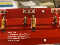
Thanks, Russel! Also for your PMs on the subject. I checked Nelsons BA-2 article, and in thr end decided to go for 0,47 source resistors. Nelson does not say that you MUST reduce source resistance with less than 6 pairs of MOSFETs. However he suggests it be reduced in proportion, and says it might be the best choice. So half as many transistors as the original 6 pir BA-3, equals 0,5 ohm source resistors. So I went for 0,47. Bought CPFs from Vishay, and the same kind of MILSPEC Vishay RNs that 6L6 used. My first PCB soldering job complete, and only MOSFETs left to do on the output boards.
Attachments
On that note, I ask: What preamp should my soon to be beautiful BA-3 be paired with?
What is good about the IronPre?
What about B1 buffer, or B1 Nutube? Or BA-3 preamp?
With BA-3 which is a kind of "power buffer" you need lots of gain... B1 buffer, B1 Nutube have no gain. So it won't work. IronPre has 6 or 12dB it won't be enough (12dB could be enough if you have HR speaker).
BA-3 pre is a perfect match.
I will use IronPre 6dB version to drive the "complete" BA-3 (meaning BA3 FE and complementary output PCB). If I have too much gain, I will decrease it changing resistor value on BA3-FE.
I just hope they gonna match together... After that I will try a classe B power amp by Plantefeve
driven by the IronPre 
Damien
The front-end is a very close relative of the F5, with no feedback and with the extra mosfets to give drive oomph to the output stage.
The output stage is identical to the F4.
As one would expect it sounds like a cross between an F5 and an F4, keeping the best points of each. I really like it.
The Front-end has enough gain to drive it to full output from less than 2V in, so no preamp is strictly necessary.
Abx: According to this, the B1 and B1 Nutube should work fine, or am I wrong?
B1 Korg (NuTube) has a good 16dB of gain. I would actually also consider Wayne BA2018 preamp.
How much gain you need from a preamp really depends on how loud you listen, how much output
you get from your source, etc. For me, unless I'm using my F4 or Mofo,
I am fine with even with an IronPre configured for 6dB gain.
How much gain you need from a preamp really depends on how loud you listen, how much output
you get from your source, etc. For me, unless I'm using my F4 or Mofo,
I am fine with even with an IronPre configured for 6dB gain.
Thanks, Russel! Also for your PMs on the subject. I checked Nelsons BA-2 article, and in thr end decided to go for 0,47 source resistors. Nelson does not say that you MUST reduce source resistance with less than 6 pairs of MOSFETs. However he suggests it be reduced in proportion, and says it might be the best choice. So half as many transistors as the original 6 pir BA-3, equals 0,5 ohm source resistors. So I went for 0,47. Bought CPFs from Vishay, and the same kind of MILSPEC Vishay RNs that 6L6 used. My first PCB soldering job complete, and only MOSFETs left to do on the output boards.
You are going to love BA3.
- Home
- Amplifiers
- Pass Labs
- BA-3 Amplifier illustrated build guide