Pass B1 as a buffer ...
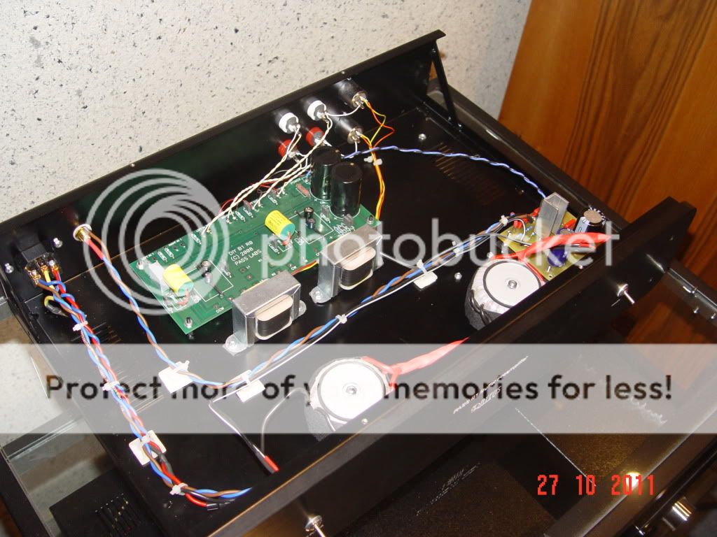
The resistors are Caddock, input caps are Auricap and on the output I put BlackGates STD 200 uF. Output resistor is 50 Ohm instead of 1 KOhm. For balancing conversion I use really excellent Jensen transformers. 10 mF Mundorfs are in the supply, 1 Ohm resistor is Mills and wiring is silver-gold Mundorf wire.
Connectors are silver WBTs and XLR Furutech. IEC is also Furutech. Power supply is regulated with LM317 for 24 V DC. Transformer is 20 VA. (the other one is for supply of relays of my passive TVC).
It works really well ...
Nice work dejanm. Do you use the buffer before or after the TVC?
I am using it after the TVC in order to reduce the impedance of the TVC.
I am using copper S&B transformers of the third generation in my TVC preamp. It has 24 positions of about 2 dB attenuation per position. Output impedance varries depending on the position but in average it is about 1 KOhm or a bit more than that. Now, after exchanging 1 Kohm output resistor of original Pass schematic with 50 Ohm one in this buffer, I have output impedance of about 100 Ohm.
I would be very interested in seeing info about the relay switching of the TVC's if you care to post.
Here it is:
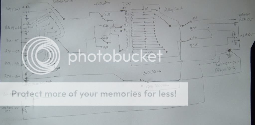
Unfortunately Marra I do not have it anymore (TVC was finished in 2007). I only have this picture - maybe it can be of any help ... I ordered this PCB - it was done by profi's not by me ...
 [/IMG]
Basically the implementation is straight-forward connecting the switches and Shallco selector with the relays ...
Basically the implementation is straight-forward connecting the switches and Shallco selector with the relays ...
Thanks. I don't suppose you know if the relay boards are still available?
I can connect you with the guy who made them for me so you can make a deal (or not) directly with him ... if you want. Send me a PM if you need more information.
I have never used these audio drivers before , are they polarised ?
I'm guessing they are and the dot on the board should match the dot on the part ?
http://www.farnell.com/datasheets/1360574.pdf
I'm guessing they are and the dot on the board should match the dot on the part ?
http://www.farnell.com/datasheets/1360574.pdf
Last edited:
Hi,
balanced signals have two phases that are 180degrees apart.
If the half signal drops below +0.0V then this requires a dual polarity supply.
If you are asking can the chip be swapped around in it's socket, then no. All dip 8 chips have a marking indicating PIN1. This must be aligned with the PCB correctly to allow the chip to get the correct signals on all of it's pin.
The only chip I am aware of that does not get destroyed by inverting it in it's socket is the 741.
Thanks Andrew ,
I found a photo showing the correct orientation - it appears my guess was correct .
I have managed to make a supposedly simple build even more complicated . The great thing is , a few have been there before me .
I would advise everyone on the forum to buy shares in solder wick")
Rich
I found a photo showing the correct orientation - it appears my guess was correct .
I have managed to make a supposedly simple build even more complicated . The great thing is , a few have been there before me .
I would advise everyone on the forum to buy shares in solder wick
Rich
I have been thinking about using this for my Balanced B1 .... opinions are welcome please ?
Glasshouse Takman metal stepped attenuator Hifi Collective
Rich
Glasshouse Takman metal stepped attenuator Hifi Collective
Rich
I have been thinking about using this for my Balanced B1 .... opinions are welcome please ?
Glasshouse Takman metal stepped attenuator Hifi Collective
Rich
I have bought the same (also for a B1) but Jaap (my friend who does the building for me) is still working on my F4's. Have no idea how they will sound.
- Status
- This old topic is closed. If you want to reopen this topic, contact a moderator using the "Report Post" button.
- Home
- Amplifiers
- Pass Labs
- B1 builders thread