crt said:
This is my B-1 Buffer - Salas Version
I clearly Hear a Different between them.
BUT I WILL NOT LEAVE A COMMENT
Regards
La Ode
Can you post the PCB details? It looks very neat, and forum members can benefit. Its cheap and compact without the high grade couplers.
crt mailed me the layout which is neat indeed. It could use more decoupling though and it would benefit from some refinements in the power supply section. I updated the schematic but since I am a beginner with Eagle I could only draw the new schematics but how to layout the PCB was too complicated for me.
Who takes the challenge ? If crt agrees I could post the updated schematics.
Who takes the challenge ? If crt agrees I could post the updated schematics.
@Salas
this is my layout, with a little modification
layout
mail me at ----- tjeret@gmail dot com,
if you want the files in eagle, pdf, or maybe bitmap.
Actually my layout have two jumper.
1. for V- (top jumper)
2. for Ground (bottom jumper)
@Jean-Paul
post the schematic here please
i will try to make the layout as long as i can.
I like it. Very neat. I guess that a pdf link of the copper side negative along a 1cm line actual print size guide on it, will be enough for most. Maybe the silkscreen mask on an alike pdf link too. Thanks. Me I have a B1 without capacitors as you know, but I guess its nice it can be repeated by members since you have done a nice PCB for it. Which one stays in your system? Capacitor coupled with single PSU, or non caps with symmetric PSU one?
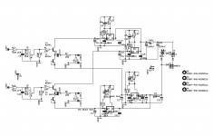
This is the updated schematic. I hope I did it right with Eagle....
I included double supplies and a Alps RK27 for volume. The 10 uF output cap can be jumpered for the aforementioned offset issues ( if they are a real issue that is ).
crt, please try to only jumper + and/or -, not GND.
As the file is too big I had to make it fit. Crt, if you want the original, I have mailed it to you.
Attachments

jean-paul said:This is the updated schematic. I hope I did it right with Eagle....
I included double supplies and a Alps RK27 for volume. The 10 uF output cap can be jumpered for the aforementioned offset issues ( if they are a real issue that is ).
crt, please try to only jumper + and/or -, not GND.
As the file is too big I had to make it fit. Crt, if you want the original, I have mailed it to you.
Is this a BJT version of the B1? I'd be interested. Please send me the full scale schematics etc., by mail. Thanks.
No ! I guess 2SK170 was not in the library as crt choose BC types. This is not a BJT version.
To crt ( La Ode ): I have downloaded the free version of Eagle to open your files. I edited the file and saved it. When you download the most recent free version you can read and edit them as well.
To crt ( La Ode ): I have downloaded the free version of Eagle to open your files. I edited the file and saved it. When you download the most recent free version you can read and edit them as well.
@Salas
Sorry, i Mean Jean-Paul.
Like Salas says, its not BJT version. I use BC546 because they have same pinout.
I have rebuild the B-1 like your schematic.
and this is the result.

Because i want to make symetric layout, so i have to mirrored the right side. so if you want to attach a Alps pot. that wanna be easy.
BUT :
-have a jumper for the input supply to all IC regulator ( i wanna be fair to both channel)
-for the rail resistor (10 ohm) what rated ? 1/2 watt. 1Watt?
i had give a option to parallel the rail resistor (3)
- and sory i cannot find a alps pot in my eagle library
if you want the eagle file so you can modified.
i will send to you tomorrow
Ragards
La Ode
Sorry, i Mean Jean-Paul.
Samuel Jayaraj said:
Is this a BJT version of the B1? I'd be interested. Please send me the full scale schematics etc., by mail. Thanks.
Like Salas says, its not BJT version. I use BC546 because they have same pinout.
jean-paul said:No ! I guess 2SK170 was not in the library as crt choose BC types. This is not a BJT version.
To crt ( La Ode ): I have downloaded the free version of Eagle to open your files. I edited the file and saved it. When you download the most recent free version you can read and edit them as well.
I have rebuild the B-1 like your schematic.
and this is the result.
Because i want to make symetric layout, so i have to mirrored the right side. so if you want to attach a Alps pot. that wanna be easy.
BUT :
-have a jumper for the input supply to all IC regulator ( i wanna be fair to both channel)
-for the rail resistor (10 ohm) what rated ? 1/2 watt. 1Watt?
i had give a option to parallel the rail resistor (3)
- and sory i cannot find a alps pot in my eagle library
if you want the eagle file so you can modified.
i will send to you tomorrow
Ragards
La Ode
Hi La Ode, the PCB becomes nicer with time but there should be caps before the 10 Ohm resistor. A 1/2 Watt type is OK for the 10 Ohm resistor as current draw is low. Please check the schematics for the extra 2200 uF caps. The jumpers to the regulators do not seem necessary IMO.
If the inputs would be at one side and the outputs at the other side wiring the PCB would be easier. The potentiometer would be at the lower right side ( seen from above ) and the outputs at the upper middle of the PCB straight to the output RCA connectors. Power connectors could be at the left side. Just like you would fit it in the enclosure.
You can still add the output relay like salas did to avoid nasty pops when the thing is powered when the amp is already on. We all like to think such things do not happen but they do
You can find the RK27 library and other interesting files here:
http://tangentsoft.net/elec/parts/eagle/files/audio-pots.lbr
dejanm said:
These are some experiences that might help somebody. My personal conclusion is that B1 is made as a simple buffer and that it should be kept simple. Maybe some experiments with input and output caps would be interesting (for example with Auricaps) but power supply should be done correctly but there is no real need for some extravaganza ...
http://i277.photobucket.com/albums/kk50/dejan2604/PassB1.jpg
that's a good experiences.
thanks for your share
jean-paul said:
The best cap is no cap.
The meaning clear . . .
But, no cap always sounds better than any cap . . . ???
this definition of best clearly does not apply when the cap is the only form of blocking DC or voltage mismatches.jean-paul said:The best cap is no cap.
AndrewT said:this definition of best clearly does not apply when the cap is the only form of blocking DC or voltage mismatches.
That would be sonically best when it is technically possible to cut out the caps without the mentioned risks. I consider this common knowledge.
On the other hand I see preamps, cdplayers etc. with output caps connected to amps with input caps which makes it 1 cap too many.
- Home
- Amplifiers
- Pass Labs
- B1 Buffer Preamp