Pendergast said:Hi!
Here is my contribution:
B1 in a box
It was mounted p2p on plexiglass. Fun project. I use it between an audiosector DAC and a SEX integrated amp from Bottlehead.
Really cool. Merci Monsieur Pass!
fugly!!
now you need just 3 layers of any organic oil ..... or Dammar ;
that box is 10 times worthier than DACT
")
B1 with SSM2135 Subwoofer Filter on output
I'm in the process of putting a B1 after my volume control and source selector and my Pearl Phono boards to drive my amp, (Hafler 9505 now, Bridged F5 later). Right now I am using an Outlaw ICBM to split the low pass to my Vandersteen V2W subwoofer. The ICBM has both parametric X-over frequency selection and gain control to match the subwoofer output to the main speakers, (3A Signatures now, Quatros soon), but is overkill unless you use it in a 5.1 system.
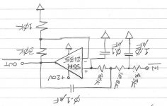
I am looking at building a fixed 60hz 3-pole X-over with 12 dB of gain using an Analog Devices SSM2135 op amp. The beauty of the SSM2135 is that it can run from a single supply, like the B1 and the Pearl boards, and I can get one from Digikey for 6 bucks. Input would come from the output of the B1 buffer. Output would run into a 10K trim pot and then onto the V2W. The circuit is attached.
This chip is used in IO circuits of PC sound boards and reportedly sounds pretty good - probably good enough for a subwoofer. Have any of you guys tried one of these in any of your circuits ??
I'm in the process of putting a B1 after my volume control and source selector and my Pearl Phono boards to drive my amp, (Hafler 9505 now, Bridged F5 later). Right now I am using an Outlaw ICBM to split the low pass to my Vandersteen V2W subwoofer. The ICBM has both parametric X-over frequency selection and gain control to match the subwoofer output to the main speakers, (3A Signatures now, Quatros soon), but is overkill unless you use it in a 5.1 system.
I am looking at building a fixed 60hz 3-pole X-over with 12 dB of gain using an Analog Devices SSM2135 op amp. The beauty of the SSM2135 is that it can run from a single supply, like the B1 and the Pearl boards, and I can get one from Digikey for 6 bucks. Input would come from the output of the B1 buffer. Output would run into a 10K trim pot and then onto the V2W. The circuit is attached.
This chip is used in IO circuits of PC sound boards and reportedly sounds pretty good - probably good enough for a subwoofer. Have any of you guys tried one of these in any of your circuits ??
Attachments
salas:
Thanks for share your projects in this forum
Is that Antek 10VA trafo, AN-0120, too tiny to power your 28V DC shunt reg PSU.
http://www.antekinc.com/AN-01xx.pdf
Thanks
Thanks for share your projects in this forum
Is that Antek 10VA trafo, AN-0120, too tiny to power your 28V DC shunt reg PSU.
http://www.antekinc.com/AN-01xx.pdf
Thanks
AndrewT said:Hi,
Does the single supply opamp require DC blocking caps on the input and output?
May also need a blocking cap a the bottom of the 10k / 30K connection to gnd, and usually needs a method provide b+/2 to the + input, usually done with 2 large resistors, or as is done in the B1 (more parts= better)
B1
BFNY-
I've been wondering about the effect of resistance and capacitance to ground. You just mentioned that it might be an advantage in the x-over schematic- what is the basis of this design feature and can you point me to more info on the subject- I found varied resistance in the various gound leggs of my star grounded b-1 had positive effcts on general noise levels but don't understand the mechanism-
some light at "the mouth of this cave" would be appreciated-
thanks
rob
Blocking Caps
Gents, the B1 already has a blocking cap for the input. I would use a 220 Silmic electrolytic and 0.1 mfd film on the output prior to the trimmer - not sure if I need to put it AHEAD of the feedback path, though. (BTW, the input impedance of the Vandy V2W is 100K ohms - I MIGHT be able to just use a big film cap on the output, given a higher valued trimmer pot. )
The SSM2135 application notes don't show this for a single supply headphone amp - see Fig. 31.
Re: B1 with SSM2135 Subwoofer Filter on output
Is single supply beauty ? Dual supplies can cancel out caps which comes closer to beauty IMO
dcbingaman said:The beauty of the SSM2135 is that it can run from a single supply, like the B1 circuit
Is single supply beauty ? Dual supplies can cancel out caps which comes closer to beauty IMO
The Beauty of Single Supply
From scratch, dual supply allows direct coupling and so is preferred. Since I am adding this to an existing Pearl Phono, I've already go a nice 2A / 40VDC remote power supply which I can tap from. I can drop this to 25V with an LT1085CT IC voltage regulator for the B1 buffer board and the low pass filter without much pain or perturbation of the Pearl regulators.
Adding another +[/U] raw power supply and negative voltage regulator is a much bigger pain-in-the @#$. Hence, single-supply for this application is very attractive.
I'm not crazy about the SSM2135 SOIC package....my 54-year old eyeballs may not be up to the challenge of soldering this little dude to my prototype board pins....any of you modketeers have any tips on how to do this, (besides buying three of them to account for "F-ups" ??)
Re: The Beauty of Single Supply
Put some solder down on one pad and hold device in place while you reflow the solder to seat it down. Once that is done just heat and solder all the pins not worring about bridging. Let the device cool down. Then pull out the solder Wick (Braid) and a wide tip iron place the wick on the SMD pads and draw off all the the access solder. This usually works fine as enough solder is left around the leads and and wicked under them to make a good electrical connection. Be careful not to over heat the device, I use an IR Thermometer to be anal, but just be careful and you should be fine.
Anthony
dcbingaman said:From scratch, dual supply allows direct coupling and so is preferred. Since I am adding this to an existing Pearl Phono, I've already go a nice 2A / 40VDC remote power supply which I can tap from. I can drop this to 25V with an LT1085CT IC voltage regulator for the B1 buffer board and the low pass filter without much pain or perturbation of the Pearl regulators.
Adding another +[/U] raw power supply and negative voltage regulator is a much bigger pain-in-the @#$. Hence, single-supply for this application is very attractive.
I'm not crazy about the SSM2135 SOIC package....my 54-year old eyeballs may not be up to the challenge of soldering this little dude to my prototype board pins....any of you modketeers have any tips on how to do this, (besides buying three of them to account for "F-ups" ??)
Put some solder down on one pad and hold device in place while you reflow the solder to seat it down. Once that is done just heat and solder all the pins not worring about bridging. Let the device cool down. Then pull out the solder Wick (Braid) and a wide tip iron place the wick on the SMD pads and draw off all the the access solder. This usually works fine as enough solder is left around the leads and and wicked under them to make a good electrical connection. Be careful not to over heat the device, I use an IR Thermometer to be anal, but just be careful and you should be fine.
Anthony
Re: B1
I was referring to the circuit that references the op-amp input to a mid point between the supply voltage and ground. Same as used on the input to the B1. I didn't mean to say it was an advantage, rather try to politely say it is a requirement for a single supply op-amp (as a single stage) to work correctly.
If the B1 feeds the crossover, you may likely kill 2 birds with one stone and skip the output cap on the B1, and let the Vcc/2 present on the B1 output be the Vcc/2 input reference for op-amp.
see more on single supply op-amp design here in the first 4 pages
(sections 1.1 to 1.3, a short read). Note the non-inverting example shown in fig. 3, (pg. 6) and use of R1 and R2 connected to Vcc/2. I was suggesting using a coupling cap there to ground instead.
http://www.eng.yale.edu/ee-labs/morse/compo/sloa058.pdf
rob lenk said:BFNY-
I've been wondering about the effect of resistance and capacitance to ground. You just mentioned that it might be an advantage in the x-over schematic- what is the basis of this design feature and can you point me to more info on the subject- I found varied resistance in the various gound leggs of my star grounded b-1 had positive effcts on general noise levels but don't understand the mechanism-
some light at "the mouth of this cave" would be appreciated-
thanks
rob
I was referring to the circuit that references the op-amp input to a mid point between the supply voltage and ground. Same as used on the input to the B1. I didn't mean to say it was an advantage, rather try to politely say it is a requirement for a single supply op-amp (as a single stage) to work correctly.
If the B1 feeds the crossover, you may likely kill 2 birds with one stone and skip the output cap on the B1, and let the Vcc/2 present on the B1 output be the Vcc/2 input reference for op-amp.
see more on single supply op-amp design here in the first 4 pages
(sections 1.1 to 1.3, a short read). Note the non-inverting example shown in fig. 3, (pg. 6) and use of R1 and R2 connected to Vcc/2. I was suggesting using a coupling cap there to ground instead.
http://www.eng.yale.edu/ee-labs/morse/compo/sloa058.pdf
B1 + Preamp
Rob, great suggestion (Vcc/2) and it could save a coupling cap, however, I am also tapping the B1 output, prior to the subwoofer filter, to feed a phase-splitting transformer out to the main balanced-input amps. The subwoofer requires an unbalanced feed and I wanted to add some gain at its input along with the filtering to guard against the potential of a large sensitivity difference between (future) amps. It is really not that bad a coupling problem on the output anyway - since the V2W has a 100K ohm input impedance, using a 25K trimmer pot and seting a 5 hz, -3 db point, the coupler only needs to be ~ 1.5 mfd.
Just to make matters more complicated, I am also building a bypass relay (6PDT) into this thing so it can drive both my L &R speaker and subwoofer amps, WITHOUT going through my 7.1 surround sound processor (an Onkyo PR-SC885) in one mode and direct connect the SSP to the amps in the other mode - the best of both worlds, (maybe) !!
Soldering little bugs
Anthony - I like your suggestion - I've also heard folks use double-sided tape to hold the little devils in place on an SOJ-to-DIP adapter PCB.
In your experience, however, is it better to try this before or after a nice glass of Balvanie Scotch ??
Anthony - I like your suggestion - I've also heard folks use double-sided tape to hold the little devils in place on an SOJ-to-DIP adapter PCB.
In your experience, however, is it better to try this before or after a nice glass of Balvanie Scotch ??
No Volume
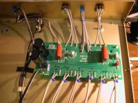
Anyone run into a low or no volume problem? I built according to original plan with no mods. I used the Pass board and an 18 volt wall wart. I thought it might be the power supply and bought another one at 24 volts but had the same problem. There is barely perceptable volume. My input is a sony DVD and my amp is an Audaire Forte dual mono amp. Here is a picture of the B1 using an old server chasis:
Anyone run into a low or no volume problem? I built according to original plan with no mods. I used the Pass board and an 18 volt wall wart. I thought it might be the power supply and bought another one at 24 volts but had the same problem. There is barely perceptable volume. My input is a sony DVD and my amp is an Audaire Forte dual mono amp. Here is a picture of the B1 using an old server chasis:
Attachments
silent b1
one question and one suggestion
check that you have voltage on the board- positive 18 or 24 volts at a transistor to ground- remember this buffer draws very little amps so if the positive volts are there you are probably ok
assuming you didn't burn the transistors soldering them(and from the photos it looks like you did a nice job), the my guess would be the volume pots- wired backwards or shorted out- by pass them with a 25k ohm resistor and, a small prayer if you are of that persuastion-
hope it goes better
rob
Re: No Volume
I would check to make sure that wrong resistor was not put in signal path. ie 1M instead of the 1K.
brutepuppy said:Anyone run into a low or no volume problem? I built according to original plan with no mods. I used the Pass board and an 18 volt wall wart. I thought it might be the power supply and bought another one at 24 volts but had the same problem. There is barely perceptable volume. My input is a sony DVD and my amp is an Audaire Forte dual mono amp. Here is a picture of the B1 using an old server chasis:
I would check to make sure that wrong resistor was not put in signal path. ie 1M instead of the 1K.
silent b1
nice call tea-bag-could be
I will say that my 25kohm in line resistor(no vol pots on my b1) left me with lots of gain for my dynaco st70 from an es sony cd/sacd player.
I don't get over 40 out of 65 with my R-2R attenuator/l switcher upstream from the b1. Course my spks are only 4 ft away, (ie nearfield) and fairly effecient( my guess 88-89db)and I don't listen loud. Old audio saleman/installer- damn kids with their loud rock and roll!
dont get me started
r
- Home
- Amplifiers
- Pass Labs
- B1 Buffer Preamp