If the main amp has an input cap or a DC fault tripping output relay, it's a no brainer to get rid of the cap. I would argue about a DC null servo loop around a capacitor-less B1, but its rather a strech given the keep it simple concept. Of course as given by Mr. Pass it is the most practical for everybody. At least the symmetric supply is very doable, and losing the input cap is a big deal subjectively with such a low component count. Using really good caps 1 & 5 μF can easily cost as much as 20 basic B1s. There is economic benefit if targeting a luxury construction in other words.
Nice answers guys, appreciated.
If I can beg a litle more help...
Assuming I go dual rail, the input cap can be removed - is there any problem caused by DC on input from source?
My power amp has dc gain of 1 (cap in feedback), so I can live with some mv of offset from removing output cap. I matched fets to within 0.1 or 0.2 ma Idss; would anyone care/dare to suggest a likely offset? I can't tightly thermally couple with my layout.
TIA
BURNER said:Thanks Choky and Stefano, I'll try to reduce R105 - 205 and see how it will go.
Hi Choky
I just did parallel 221K to R101 and R205, so it's about 110K.
Sadly enough, the offset stayed at 400mV on start-up then declined after few minutes.
My next experiment
1. Match idss of K170 as closed as possible
2. Replace output cap
3. Thermal environment control
float said:Nice answers guys, appreciated.
If I can beg a litle more help...
Assuming I go dual rail, the input cap can be removed - is there any problem caused by DC on input from source?
My power amp has dc gain of 1 (cap in feedback), so I can live with some mv of offset from removing output cap. I matched fets to within 0.1 or 0.2 ma Idss; would anyone care/dare to suggest a likely offset? I can't tightly thermally couple with my layout.
TIA
Yes, with DC at input, the operating point will shift, and the DC will pass at the output too. Check all your likely sources. Its not common to find substantial DC from sources like CD players.
Don't try to predetermine a likely offset, or possible changes over time.
Build it, use an output cap, connect it up, listen, let it burn in, and then probe for voltage before the cap. Sample cold start, warm up, equilibrium, and hourly values for a day. If its behaving decently, dare remove the cap. Listen, let us know.
That is what I would do.
would anyone care/dare to suggest a likely offset?
My suggestions for the offset to be expected:
1. This being a follower, the output offset will be the same as the input offset + the intrinsic offset of the particular Jfet pair, i.e. it will "follow" the input offset
2. Intrinsic offset rough estimate, assuming a – low - transconductance of 20 mS or 20 mA/V: Jfet mismatch/delta in mA / 20 [mA/V]. So for a 0,2 mA mismatch somewhere around 10 mV. Maybe even less if you have higher transconductance ?
salas said:
Yes, with DC at input, the operating point will shift, and the DC will pass at the output too. Check all your likely sources. Its not common to find substantial DC from sources like CD players.
Thanks Salas, Martin - there seems to be little to fear and much to gain ( 2 caps gone ) in the dual rail approach.
On the quoted point above, I've looked at some jfet tutorials, but I don't fully understand operating points

What effect would, say, 0.5 volts input offset have on performance? Does it just lower the clipping point?
It will move up the center line of the waveform by 0.5V, it will rob that from available headroom and it will translate to some 2nd harmonic also. That 0.5V it will appear at the output.
I have introduced -0.9V DC offset by asymmetric positive rail, using a resistor between B+ and upper FET. See what happens. Moves down in that case.
BTW, if you need a trimmer to null positive offset, you have to introduce it in the upper side. If you want to null negative offset, you do it vice versa. Or you use 2 trimmers and you match whatever JFET or PSU irregularities.
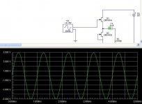
Pic1. No offset:
I have introduced -0.9V DC offset by asymmetric positive rail, using a resistor between B+ and upper FET. See what happens. Moves down in that case.
BTW, if you need a trimmer to null positive offset, you have to introduce it in the upper side. If you want to null negative offset, you do it vice versa. Or you use 2 trimmers and you match whatever JFET or PSU irregularities.
Pic1. No offset:
Attachments
salas said:If the main amp has an input cap or a DC fault tripping output relay, it's a no brainer to get rid of the cap. I would argue about a DC null servo loop around a capacitor-less B1, but its rather a strech given the keep it simple concept. Of course as given by Mr. Pass it is the most practical for everybody. At least the symmetric supply is very doable, and losing the input cap is a big deal subjectively with such a low component count. Using really good caps 1 & 5 ¼F can easily cost as much as 20 basic B1s. There is economic benefit if targeting a luxury construction in other words.
I already have a dual supply and therefore is the step to a servo solution close.
What type servo would be recomended?
I have found one from a Denon preamp used in JFET buffer output:
Op-amp type NMJ4558 (I will use LF412
From output of buffer 20K series and 20K to ground voltage devider and the to inverting input.
From inverting input to opamp output is 1uF
From non-inverting input to ground is 10K i parallel with 10uF
From output of opamp to JFET gates is 100K
Will this circuit work well or are there better alternatives?
I already have a dual supply and therefore is the step to a servo solution close.
What type servo would be recomended?
If you want to build a bipolar version of the B1 to get rid of the caps I would strongly suggest to use closely matched JFets or a dual 2SK389. Offset should not be an issue, you should be able to get down to a few mV.
With a circuit as simple as the B1 a servo would by complete and utter overkill, in my esteem. Besides, from all accounts, a badly executed servo should sound much worse that an output cap. If you are concerned about the low offset put in a cap as in the original version.
Just my 2 cents.
MRupp said:
If you want to build a bipolar version of the B1 to get rid of the caps I would strongly suggest to use closely matched JFets or a dual 2SK389. Offset should not be an issue, you should be able to get down to a few mV.
With a circuit as simple as the B1 a servo would by complete and utter overkill, in my esteem. Besides, from all accounts, a badly executed servo should sound much worse that an output cap. If you are concerned about the low offset put in a cap as in the original version.
Just my 2 cents.
Hi,
I understand your arguments, but:
1. Why use +100$ for audiophike capacitors if they can be avoided with >1$ components? The other thing is part size....
2. Capacitors do not sound as good without voltage accross them
3. I was not thinking of a bad servo, but a good one
4. I have allready matched JFETs in circuit (9.53 and 9.55mA)
5. I have low offset, but would like the servo for longterm drift and safety. I do not have DC-protection...
Then put it around the buffer. If you don't notice sonic degradation, post the final schematic. But if you monitor your bipolar B1 for let's say a week and shows under 10mV, it may be safe. Keep a voltmeter on the speaker binding posts so to see what the worse case translates there. How much is your offset now?
salas said:Then put it around the buffer. If you don't notice sonic degradation, post the final schematic. But if you monitor your bipolar B1 for let's say a week and shows under 10mV, it may be safe. Keep a voltmeter on the speaker binding posts so to see what the worse case translates there. How much is your offset now?
I think I might just do that....my current offset at peakers is +/-40mV
Gain in poweramplifier is 32x including DC....
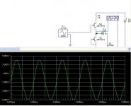
salas said:Pic2. -0.9V DC offset:
Thanks again Salas.
BTW, could the distortion in your second image (0.9 offset) have anything to do with a 10v signal and only 9v power supply?
Skorpio said:
I think I might just do that....my current offset at peakers is +/-40mV
Gain in poweramplifier is 32x including DC....
40mV offset at speakers when the main amp is driven by the DC coupled bipolar B1? If so, no need to worry, its next to nothing. Just make a DC sensing, relay controlling circuit for the B1's output to secure a disaster scenario in case of a fault during the system's lifetime.
float said:
Thanks again Salas.
BTW, could the distortion in your second image (0.9 offset) have anything to do with a 10v signal and only 9v power supply?
Remember that we are discussing the bipolar B1. There is a -9V B- also. It is just obscured by the sinewave foreground in the picture.
Zen Mod said:
smaller resistor from output side of cap to ground - will speed up charging ; decrease it from present 221K value to , say , 100K 0r even less
My experiment on offset
-Reduce R 221K to 110K at output to ground, it doesn't cure
-Change output cap from 10uf MKP type to electrolytic, offset increases to 900mV from cold and decreases very slow
-Change output cap from 10uf to 4.7uf SCR MKP, offset starts around 30mV and declines quite faster than 10uf MKP cap.
it looks like quality of output cap may affect to the offset as well...
any ideas?
BURNER said:
..........
it looks like quality of output cap may affect to the offset as well...
........
certainly ;
besides that - I wrote "...... even less" .
in any case - if you have problems with offset - then make small delay circuit which can switch off relay after 5-10 seconds ; relay contacts connected as short from output side to gnd
- Home
- Amplifiers
- Pass Labs
- B1 Buffer Preamp