It is my intention to build a B1 in this small case. The bottom copper plate will be ground or negative and the centre strip the + PS feed. I intend to super glue the components to the bottom copper plate.
When building the preamp is there anything I should be careful of in construction and component placing. Is the preamp stable, can it oscilate easy??
When building the preamp is there anything I should be careful of in construction and component placing. Is the preamp stable, can it oscilate easy??
Attachments
In the case of the B1, there is not a balance control other than by independently adjusting the channel gain by non-ganged pots. Even if you have a perfectly synchronized stereo pot there is still merit to using separate pots for each channel. Your ears, room, or equipment, may not entirely agree with the recording engineers.
Lae2,
I am having a second thought on the pot. How about this one:
Gigawork Stereo Pot
It's a Log 50K. It also has 100K and 20K version. Would it work on Pass B1?
Lae2,
I am having a second thought on the pot. How about this one:
Gigawork Stereo Pot
It's a Log 50K. It also has 100K and 20K version. Would it work on Pass B1?
Wow, that is quite a price if all is on the up and up. You might take a look at the Dick Olsher review. IIRC, he preferred a 50K over the 25k input resistance. He is also favorable toward non-ganged volume controls. At 10 bucks you might buy two and try unganged or ganged to see what you prefer. I realize that most builders appear to be using stereo pots. Frankly, this puzzles me. Even with the most precise pots you can expect differences in balance at low volume settings. Not to mention that your ears, room, and equipment may have subtle asymmetries at low volume. I would opt for unganged pots.
it is fed from a non zero source impedance (the pot) that varies.
It is supplying a load that is not infinite.
The approximate way to guessimate the turnover frequency is to find the effective load impedance and assume that the non zero source has only a small effect.
The load impedance is the 1k0 + the 221k in parallel with Zin of the next stage.
If the next stage has Zin=10k then the load impedance is 221//10=221*10/(221+10)=9k57.
Now add the 1k0 series resistor giving 10k57.
The RC time constant is 106mS using the 10uF DC blocking cap.
If the power amp also has a DC blocking cap, you need to look at the input filter formed there as well. But this time you have two caps in series and need to account for the series pair in your calculation.
Andrew, do you have a recommendation for optimal B1 output cap/resistor values for an amp with 7.5k input impedance and 22uf input caps?
The problems is the non-audiophile sees at as too hard to have to adjust two pots. Just for sheer laziness they will take a single knob over two knobs any day.Wow, that is quite a price if all is on the up and up. You might take a look at the Dick Olsher review. IIRC, he preferred a 50K over the 25k input resistance. He is also favorable toward non-ganged volume controls. At 10 bucks you might buy two and try unganged or ganged to see what you prefer. I realize that most builders appear to be using stereo pots. Frankly, this puzzles me. Even with the most precise pots you can expect differences in balance at low volume settings. Not to mention that your ears, room, and equipment may have subtle asymmetries at low volume. I would opt for unganged pots.
The problems is the non-audiophile sees at as too hard to have to adjust two pots. Just for sheer laziness they will take a single knob over two knobs any day.
Hey now.
 If you're listening to different types of music with different volume levels it gets to be a pain to get up over and over and adjust both knobs to just the right setting, especially if you are trying to be perfectionist and compensate for any sensitivity/room anomalies.
I have an upgraded Oppo 980H which has a volume control on the remote. For me it is more about getting the balance and max volume right then letting the Oppo do the work.Hey now.
I have an upgraded Oppo 980H which has a volume control on the remote. For me it is more about getting the balance and max volume right then letting the Oppo do the work.
ah. the 980H. I don't use it so much anymore since I put everything on hard drive, but I'll never part with it...
Back on topic-ish: I'm guessing you post on the other diy site/forum. How do you think the B1 compares to that tiny tube kit preamp you wrote about last year?
I'm yet to build the B1 but I will let you know.ah. the 980H. I don't use it so much anymore since I put everything on hard drive, but I'll never part with it...
Back on topic-ish: I'm guessing you post on the other diy site/forum. How do you think the B1 compares to that tiny tube kit preamp you wrote about last year?
Wow, that is quite a price if all is on the up and up. You might take a look at the Dick Olsher review. IIRC, he preferred a 50K over the 25k input resistance. He is also favorable toward non-ganged volume controls. At 10 bucks you might buy two and try unganged or ganged to see what you prefer. I realize that most builders appear to be using stereo pots. Frankly, this puzzles me. Even with the most precise pots you can expect differences in balance at low volume settings. Not to mention that your ears, room, and equipment may have subtle asymmetries at low volume. I would opt for unganged pots.
So if I buy two, I'll be able to use two stereo pots as two mono pots if I like?
Sw
Is their a bom, what part number for toggle switch ?
toggle switch
Is their a bom, what part number for toggle switch ?
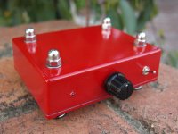
It is my intention to build a B1 in this small case. The bottom copper plate will be ground or negative and the centre strip the + PS feed. I intend to super glue the components to the bottom copper plate.
When building the preamp is there anything I should be careful of in construction and component placing. Is the preamp stable, can it oscilate easy??
The only problem I see with building in this case is that unless you build it point to point, the case is too small to fit the PCB from Pass DIY.
Peace,
So if I buy two, I'll be able to use two stereo pots as two mono pots if I like?
Yes, you would simply use one section of each pot per channel for unganged two channel volume control. The other section of each pot would not be connected. You are looking at stereo pots that are less that 1/10 the cost of what I paid for seemingly similar mono pots. From that perspective, 20 bucks to use only half the pot does not sound bad. Unless you can find mono stepped pots at an even better price. Please do keep us informed about these pots should you order them.
It is my intention to build a B1 in this small case. The bottom copper plate will be ground or negative and the centre strip the + PS feed. I intend to super glue the components to the bottom copper plate.
When building the preamp is there anything I should be careful of in construction and component placing. Is the preamp stable, can it oscilate easy??
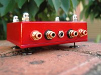
The one thing that gives me pause is using the copper plate for signal ground. I suppose that is fine if you are certain that you would never wire a chassis ground. I would weigh the merit of reserving the copper plate for a chassis ground and maintain a separate signal ground.
Depending on your other equipment, you may inadvertently connect signal ground directly to chassis ground if you one day decided to ground the B1 chassis.
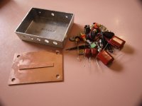
Component-2-component
Thanks for the comment.
I intend to wire component direct to component. I build all my valve amps this way to. Never use a PCB if I can avoid it.The only problem I see with building in this case is that unless you build it point to point, the case is too small to fit the PCB from Pass DIY.
Peace,
Thanks for the comment.
The RCAs are the insulated type so I can keep signal ground seperate. I'm hoping the copper plate will provide good sheilding and act as a ground plate.The one thing that gives me pause is using the copper plate for signal ground. I suppose that is fine if you are certain that you would never wire a chassis ground. I would weigh the merit of reserving the copper plate for a chassis ground and maintain a separate signal ground.
Depending on your other equipment, you may inadvertently connect signal ground directly to chassis ground if you one day decided to ground the B1 chassis.
Hi All:
I have been enjoying my B1 for a few months now. I much prefer it over other preamps I have (a passive and a tube-based). Thanks to Nelson and all others that I have learned from on this board. Unfortunately, I have a problem. Recently a breaker was tripped due to an overload of the circuit (equipment unrelated to my audio gear). This caused the power supply to the B1, a Dell laptop ps (19.5 v; 4.6 A DC output), to fail. Or so I originally thought--I ended up replacing the power supply, and the problem persisted. There is a small green LED on the power supply, and when I unplug/repower the ps, the LED lights up, and music plays normally (through both channels) for ~ 20 seconds or so when the light goes out, and music stops. If I repeat power cycling, the same thing happens. Nothing on Nelson's board looks visibly burnt or damaged (I used pretty much stock/recommended components to stuff the board). Has anyone else had a similar issue, or am I just 'lucky'
Thanks again everyone -- limits
I have not had that issue, but then again I use this to power my B1.
XPAL Power | Products : XP18000
XPAL Power | Products : XP18000
Thanks for the power supply suggestion. I might give it a try. Before I try to power it up again, though, I would like to figure a few things out: 1) Why does the power cycling cause the power supply to reset, and then quit after a few seconds? If I disconnect this power supply from the load (in this case, the B1), the green LED remains lit...almost seems like something was damaged when the AC circuit was tripped. But nothing looks out of place/damaged...
2) I suppose I could connect a 12 volt battery (or a different type of power supply) to it and see if that works, I am just concerned that I will further damage something if I try this.
Can anyone suggest things to check? I assume R1 and C1 would be the first components to see something nasty coming from power in...they just look OK, and the sound is fine until the power supply switches off...Help ;-)
limits
Thanks for the power supply suggestion. I might give it a try. Before I try to power it up again, though, I would like to figure a few things out: 1) Why does the power cycling cause the power supply to reset, and then quit after a few seconds? If I disconnect this power supply from the load (in this case, the B1), the green LED remains lit...almost seems like something was damaged when the AC circuit was tripped. But nothing looks out of place/damaged...
2) I suppose I could connect a 12 volt battery (or a different type of power supply) to it and see if that works, I am just concerned that I will further damage something if I try this.
Can anyone suggest things to check? I assume R1 and C1 would be the first components to see something nasty coming from power in...they just look OK, and the sound is fine until the power supply switches off...Help ;-)
limits
Do you have D2 installed? Does it light in accord with the B1 playing? My bet is that the B1 is fine. The "new" power supply may not like the initial charging of C1/2. There could a balance whereby C1/2 charge enough to make the B1 operate but then the PSU gives up. I would temporarily place a 1-5 ohm resister in series with R1. Doing so will further limit current flow during the charging of C1. See if the PSU remains on. This is largely academic though, I bet that you need a different PSU.
Although unlikely, C1 could have taken a hit. Check to verify that C1 has high DC resistance and that it passes the "kick" test. Measure the voltage drop across R1. IIRC, the B1 should draw about .050 A. E=IR; I=.050, R=1, .050X1= .05 Volts expected drop across R1. Maybe someone else can report their measured drop across R1. Certainly a multiple Amp PSU should handle the B1 but there may be protection circuity in the Dell PSU that "knows" that the B1 is not a healthy Dell notebook. Or, the Dell PSU might not be healthy. It would be interesting to know if it would power a an appropriate Dell notebook.
Last edited:
- Home
- Amplifiers
- Pass Labs
- B1 Buffer Preamp