col said:Horizons, you can calculate it here:
http://ccs.exl.info/calc_cr.html#first
just use the high pass section.
col.
Thanks but I am more than capable of calculating and constructing first order passive networks. What I do not understand are the benefits of using some passive parts (resistors and caps) in conjunction with active setups. I assume that the reason for this was to make active eq adjustments less radical and thus creating fewer problems overall.
I guess I will just throw a 10 ohm resistor across the DE250 and let the active xover and eq fix the rest. I will be using TrueRTA to measure in the next few days. Finally got the DCX working properly which was not an easy task.
Its the cap that you need for protection NOT the resistor. The resistor alone does nothing but drain power. What you want is the cap - for protection - and the resistor - to help smooth the DE250 impedance curves so that the cap reactance isn't so negatively affected by the roughness of the DE250 impedance curve.
CD equalization
That's exactly right, and if series resistance is added for padding, the peak that results can be quite severe. A 10dB to 20dB peak is not uncommon with padding of 10dB. At the various audio shows, I do a "Crossover Electronics 101" seminar that demonstrates this, both with Spice models and actual physical circuits that are connected and listened to. It is interesting to hear the effects of each of these kinds of circuits, sort of putting a sound with a graph. Here are the handouts given at the seminars, which show the circuit schematics and the response graphs that result from each of them:
The other thing is the driver's power response is generally flat from crossover up to 3kHz to 5kHz or so, and only then does it start to fall at 6dB/octave. So the conjugate of that is to provide flat response up to around 4kHz, and then 6dB/octave augmentation above that.
My approach has always been to use an R1/R2/C1 section following a high-pass filter, with an R1/C1 pair that provides bypassed attenuation behind an R2 resistor that sets the load on the high-pass filter of the tweeter circuit. This value is basically set a little bit large, so that the filter is slightly underdamped. This provides a shelf of flat response, followed by the necessary CD equalization above that.
The R1/R2/C1 arrangement is simple and effective, providing some isolation of the impedance ripples caused by the compression horn, it sets the damping of the high-pass filter, provides the required padding and top-octave compensation.
gedlee said:I think that you guys are forgetting that the waveguide will have a natural - 6 dB / oct fall - if its true CD, so the cap and resistor make the system flat to first order.
Eva said:This only happens when the compression driver has a perfectly flat impedance curve which is never the case. In practice, the pole from the capacitor interacts with impedance peaks and dips leading to a more uneven frequency response, uneven group delay (and a more spoiled crossover).
That's exactly right, and if series resistance is added for padding, the peak that results can be quite severe. A 10dB to 20dB peak is not uncommon with padding of 10dB. At the various audio shows, I do a "Crossover Electronics 101" seminar that demonstrates this, both with Spice models and actual physical circuits that are connected and listened to. It is interesting to hear the effects of each of these kinds of circuits, sort of putting a sound with a graph. Here are the handouts given at the seminars, which show the circuit schematics and the response graphs that result from each of them:
The other thing is the driver's power response is generally flat from crossover up to 3kHz to 5kHz or so, and only then does it start to fall at 6dB/octave. So the conjugate of that is to provide flat response up to around 4kHz, and then 6dB/octave augmentation above that.
My approach has always been to use an R1/R2/C1 section following a high-pass filter, with an R1/C1 pair that provides bypassed attenuation behind an R2 resistor that sets the load on the high-pass filter of the tweeter circuit. This value is basically set a little bit large, so that the filter is slightly underdamped. This provides a shelf of flat response, followed by the necessary CD equalization above that.
The R1/R2/C1 arrangement is simple and effective, providing some isolation of the impedance ripples caused by the compression horn, it sets the damping of the high-pass filter, provides the required padding and top-octave compensation.
Horizons said:What I do not understand are the benefits of using some passive parts (resistors and caps) in conjunction with active setups. I assume that the reason for this was to make active eq adjustments less radical and thus creating fewer problems overall.
I was suggesting some passive EQ to preserve the dynamic range of your digital crossover. If you are adding a series cap for protection, the EQ comes practically for free. The shelving filter doesn't completely block LF, but will provide substantial safety margin.
It can be done with active analog filters too. In my own system (DEQX) and low power amps, I used a line level analog filter to compensate for the roll off of the constant directivity WG. This preserves the full power of the amp at the lower end of the driver range. At the upper end, where boost is greatest, there is not much HF content, so clipping is not an issue. In this case, I don't worry too much about protection. It's a tube amp, so no DC issues. Power is not enough to fry the driver.
Sheldon
Eva said:Your documents are great but could you change the plots to log/log scale? I think that they are easier to understand that way.
One of the links in my last post has a copy of Spice you can download, complete with models of the crossovers used to generate the graphs. You can set the amplitude axis scale to voltage or decibels, and the frequency axis scale can be set to linear or logarithmic.
CD equalization
Out of band distortion products are probably less audible than the drooping response that would result from not providing the EQ.
There's not a lot of augmentation until you get above 10kHz, and what's the harmonics of that? 20kHz+ for second harmonics and over 30kHz for third and beyond.
We're talking about horns that generate over 105dB/2.83v/M below 5kHz and 95dB/2.83v/M at 15kHz. So the EQ attenuates the signals below 5kHz ten-fold, but gradually reduces the amount of signal reduction as the frequency rises. Not a lot of power required into these horns to make a lot of sound, and the distortion is also very low.
You could crossover to a super-tweeter if the thought of top-octave compensation bothers you. But I personally think the polar anomalies created by crossing over to a super-tweeter make it less desirable that providing electrical EQ for a 1" compression driver on a CD horn.
Or you could use another kind of horn that provides acoustic EQ on-axis, but then the power response is off. I guess that gets us into the discussion of whether polars are important or if on-axis is all that matters. Personally, I think controlled and uniform directivity is important.
Re: Re: CD equalization
Nonlinear distortions in compression drivers were shown in our AES paper to be inaudible at any level. So your point is irrelavent.
freeforall said:Since you guys have all this data please show some graphs of the doubling to quadrupling the harmonic and IM distortion in the treble you get by using these 'eq' crossovers in your commercial speaker designs!
Thanks!!
Nonlinear distortions in compression drivers were shown in our AES paper to be inaudible at any level. So your point is irrelavent.
Re: Re: CD equalization
Different strokes for different folks, I guess. I've found the opposite to be the case.
If you care only about a pinpoint spot on the forward axis, then this is the easy approach. But if you care about constant directivity and uniform power response, this won't work. The interaction between drivers makes the response jagged almost everywhere in the room. That ruins everything, in my opinion.
freeforall said:When I 've done this eq padding I found the top octave becomes un listenable over the long run in a home hifi system - a real tweeter is better if you want a long term low coloration speaker
Different strokes for different folks, I guess. I've found the opposite to be the case.
If you care only about a pinpoint spot on the forward axis, then this is the easy approach. But if you care about constant directivity and uniform power response, this won't work. The interaction between drivers makes the response jagged almost everywhere in the room. That ruins everything, in my opinion.
Re: Re: Re: Re: CD equalization
The drivers were EQ'd, yes. Wrong paper. This was an AES paper that we did some years ago specifically on compression driver NOT horns. Didn't sit well with a lot of people, but oh well, thats life. Truth is truth no matter how mad it makes people. The AES just went through this over a paper on the audibility of sampling rate - that really did'nt set well with people and the AES got a lot of hate mail about it. Read the latest journal about that.
freeforall said:
So raising the IM distortion was covered in that?
Is that the same paper where you proved your horns sound exactly like a dome tweeter in a blind test?
The drivers were EQ'd, yes. Wrong paper. This was an AES paper that we did some years ago specifically on compression driver NOT horns. Didn't sit well with a lot of people, but oh well, thats life. Truth is truth no matter how mad it makes people. The AES just went through this over a paper on the audibility of sampling rate - that really did'nt set well with people and the AES got a lot of hate mail about it. Read the latest journal about that.
"I know compression drivers are high in distortion up high to begin with (break up!) then when it is 6 times higher because you have it force it to be level with the midrange like with your crossovers it becomes a high distortion device- probably fine for drunks in a bar singing karaoke! . When I 've done this eq padding I found the top octave becomes un listenable over the long run in a home hifi system"
Hello freeforall
I am a bit confused by this. When this type of EQ is done in a passive network the midband response in attenuated. Just to pick an arbitrary example with 1 watt at the speaker and 10db of attenuation at 1K you would have 100mw at 1 k and 1 watt at 15K. Why is the distortion 6 times higher for the same 1 watt input??
Rob")
Hello freeforall
I am a bit confused by this. When this type of EQ is done in a passive network the midband response in attenuated. Just to pick an arbitrary example with 1 watt at the speaker and 10db of attenuation at 1K you would have 100mw at 1 k and 1 watt at 15K. Why is the distortion 6 times higher for the same 1 watt input??
Rob
The drunk one is probably who wrote that.
Distortion products are introduced while electrical energy is being transferred to the air, and while it propagates through the air. But since this transfer and propagation process is less efficient at higher frequencies, and the incoming electrical signal is pre-emphasized to compensate for this, the relationship between the amount of genuine signal and the amount of distortion products is improved rather than degraded.
Horn loaded compression drivers tend to produce lower THD than direct radiation tweeters for a given SPL level.
The THD figures of direct radiators are not usually mentioned because they are really bad. Those hi-fi dome tweeters may easily exhibit 5% THD at low levels.
Compression drivers and horns suffer from other faults, but seldom from high THD.
Actually the measured THD can be very high in a compression driver, but so what. Its not audible - its all very low order. In our study no one could hear the 25% THD measured from the drivers. THD is simply a meaningless number that relates to nothing. This has been shown time after time again. And IMD is no better. These measures have nothing at all to do with sound quality. Don't you guys (gals too ) read the literature?
) read the literature?Eva said:But since this transfer and propagation process is less efficient at higher frequencies,
Hi Eva,
You sure about that?
gedlee said:In our study no one could hear the 25% THD measured from the drivers.
THD is simply a meaningless number that relates to nothing. This has been shown time after time again.
I suppose the magic word is "power compression" ?
Funny though...distortion of various drivers has been a very hot issue lately
But I actually thought you liked "shortrings", or am I missing something ?
Measured distortion
I've measured the B&C DE250 on an Eminence H290 horn and on the Pi wood horn. In both cases, the second harmonic is less than -40dB (1.0%) at 100dB/M from 1khz to 10kHz, and less than -50dB (0.3%) third harmonic. At 110dB/M, 2HD rises to -30dB (3.0%) and 3HD is under -40dB (1.0%).
The distortion characteristics of other modern compression drivers are similar, at least those I've measured from Eminence and JBL. I have found some popular vintage drivers that rose to -20dB 2HD (10%) at 2.83v/M, but I've never seen any that rose to -10dB (30%) at this drive level, except when used out of band. Then again, I haven't measured them all.
freeforall said:Add 6 to 12 db relative to the midband when using Gedlee or Pi style HF crossover.
I don't know what Earl is doing in his crossover, but I can tell you for sure that's not the case in mine. There is no increase or reduction in distortion, whatsoever. And to tell the truth, I doubt Earl's crossovers increase distortion either. The biggest difference would be in the position and size of the vertical nulls, which are affected by the frequency and width of the overlap band.
Whatever the distortion spec of the driver/horn is without a crossover at a given SPL, it's the same when passed through my crossover at the same SPL. If you think in terms of input signal, it would be reduced in distortion from 2kHz to 6kHz, because the drive level is attenuated in that region. But if you're comparing at equal SPL, then the distortion levels are the same whether passed through the crossover or applied directly via a biamp or something like that.
"Look at the distortion at a given SPL. When the crossover is used the high frequency is raised 6-10 db relative to the mid band. This in turn raises the distortion relative to the midband by 6-10 db."
Hello freeforall
I am not sure I follow you. The power level going into the driver is lower at 1K and lets say stays at unity on the top end where there is no attenuation. You are changing the relative distortion mix but you are not making the distortion higher in the upper driver bandwidth any worse than it already was to begin with. If anything you are lowering the drive levels where you have the most excursion which can't be a bad thing.
I also question just how audible a 6db change in second harmonic distortion is at 10K when you are already 40-50db down??
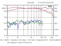
Here's a quick measurement I have of the same compression driver with and without a compensation network at the same SPL measured 1 meter away.
As I see it the actual measured distortion levels generated by the driver will be both level and frequency dependent. The passive networks does not change the distortion levels produced by the driver for a given power input at any given frequency.
Red and Green No compensation
Purple and Blue with compensation
Do you think there would be an audible difference looking at the second harmonic levels??
Rob
Hello freeforall
I am not sure I follow you. The power level going into the driver is lower at 1K and lets say stays at unity on the top end where there is no attenuation. You are changing the relative distortion mix but you are not making the distortion higher in the upper driver bandwidth any worse than it already was to begin with. If anything you are lowering the drive levels where you have the most excursion which can't be a bad thing.
I also question just how audible a 6db change in second harmonic distortion is at 10K when you are already 40-50db down??
Here's a quick measurement I have of the same compression driver with and without a compensation network at the same SPL measured 1 meter away.
As I see it the actual measured distortion levels generated by the driver will be both level and frequency dependent. The passive networks does not change the distortion levels produced by the driver for a given power input at any given frequency.
Red and Green No compensation
Purple and Blue with compensation
Do you think there would be an audible difference looking at the second harmonic levels??
Rob
Attachments
Wayne Parham said:
I don't know what Earl is doing in his crossover,
My crossovers look pretty much just like yours - I may use more RLC compensation circuits across the driver. We are both solving the same basic problem.
The rest of this discussion of THD in compression drivers is pointless.
I assumed you were using the same basic crossover topology I do, at least in respect to CD equalization. One would have to in order to get the 6dB/octave curve.
I think that other "freeforall" fellow was the same person that used large tractrix horns for many years. That would explain why he didn't like CD compensation. Tractrix horns aren't CD.
I think that other "freeforall" fellow was the same person that used large tractrix horns for many years. That would explain why he didn't like CD compensation. Tractrix horns aren't CD.
- Status
- This old topic is closed. If you want to reopen this topic, contact a moderator using the "Report Post" button.
- Home
- Loudspeakers
- Multi-Way
- B&C Compression Driver and Horns