Hi Ian,
The following are referenced to the last schematic posted. The input resistors (R18, R28) are 10K. The SuSy feedback resistors (R16, R30) are 221K. The input JFET gate to ground resistors (R19, R29) are 22.1K. The MacMillan resistors (R46, R47) are 22.1K. The cascode reference voltage setting zener should have it's cathode connected to ground (as opposed what is shown in the schematic).
My understanding of the 22K gate to ground resistors is that they make sure the amp has unity gain at DC.
I look forward to hearing the news regarding your mod.
Graeme
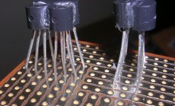
I have been thinking of a way of assembling the Jfet and holding them together.....
Anyway, the other day I was in a hardware supplier and had to make up a cash counter order to $27 dollars and they said do I need any locktite or super glue.
I figure how else can I bond my matched Jfets.
Under high magnification it does not look at neat as to the naked eye but here we are.
iMac
Anyway, the other day I was in a hardware supplier and had to make up a cash counter order to $27 dollars and they said do I need any locktite or super glue.
I figure how else can I bond my matched Jfets.
Under high magnification it does not look at neat as to the naked eye but here we are.
iMac
Attachments
Hi Dave,
Yes I still use the input coupling caps. Getting rid of them caused serious offset problems that I wasn't interested in attacking at this time. I haven't matched the 2SJ109's to each other yet. I am running them at an Id of 5ma. I agree with your comment on Erno.
I'm really busy at work and will be for a while. So I'm not doing any fun hifi things. I'll get back to stuff some time in May.
Thank you for the picture Ian. I've seen some people wrap these sorts of transistor structures with a thin piece of metal or wrap them with a single layer of thin copper wire as a heat transfer/spreader mechanism.
Graeme
 )
)If you really want good thermal coupling between the 2 FETs, then you should use a thermally conductive glue, like Artic Silver or Artic Silver Ceramics. Apply only the thinnest possible layer and press the 2 flat surfaces tightly against each other. A tool maker's clamp would be perfect for the job. Heatshrink probably more handy to most.
The heatshrink can be removed afterwards to facilitate dissipation to ambient.
Patrick
The heatshrink can be removed afterwards to facilitate dissipation to ambient.
Patrick
Graeme, Would it be too much trouble to post a schematic of your most current and successful build. I have all of the heatsink panels cut and have begun matching the parts. With a stack of 250 mosfets I will probably be matching for quite some time.
I have a question pertaining to the dc offset. Are the speakers connected to the outputs when the unit is powered up. With the large, at turn on, dc offset would not damaged occur to the speakers.
I have a question pertaining to the dc offset. Are the speakers connected to the outputs when the unit is powered up. With the large, at turn on, dc offset would not damaged occur to the speakers.
Hi tryonziess,
I am really busy these days with things other than audio projects but I will try to get the schematic up for you in the next few days.
Only the relative offset is important as far as the speakers are concerned. It is the difference between the absolute offsets on the two speaker output terminals. The downside of the absolute offset, until it drops down to around zero, is that it cuts into the total maximum output voltage swing.
The relative offset never rises above a very small value during turn-on. I hear no thump. My speakers are MG3.6's and I'm really, really careful about what I hook up to them. Everything is double and triple checked. I even have a set of small bookshelf speakers (Madisound Sledglings which I have renamed "Sacrificials") which walk the plank first whenever new electronics or mods enter the system.
Graeme
I am having some issues trying to test the Jfet paird without connecting the output fets..
To test the new parrelell pairs I wired up the driver board to a daul low current 27 volt Dc power source. The lower ZTX 450s smoked then blew.
I checked everything and it looks okay.
I dont want to risk the output stage.
Any ideas?
iMac
To test the new parrelell pairs I wired up the driver board to a daul low current 27 volt Dc power source. The lower ZTX 450s smoked then blew.
I checked everything and it looks okay.
I dont want to risk the output stage.
Any ideas?
iMac
ax100
GL, my converted Aleph amps are running great and are filling the bill as advertised running in my biamp system. After a lot of use one amp does run a bit hotter than the other but I am attributing that to the output devices since at the same bias setting they are conducting slightly more current. I didn't rematch any devices but used the ones that were already in the Aleph.
I have one question regarding your schematic, why did you choose transistors as cascodes and not other J-fets? Just curious as I reread Erno Borbely's articles on jfets in the 1999 issues of audio electronics and he uses j-fets as cascodes.
I did get some pairs of matched j74's with an iss of 7-8ma from him and I will try your circuit out when I collect the other parts.
The sound of the xa100 run full range as compared to the 350.5 and A75 seems better in the midrange and not as good as in the very deep bass. The 350.5 goes deeper but all of this could be due to the speakers impedance at low frequencies where the 350.5 has more current (I think). Anyway these are all very good designs. I have to work on getting the chasis for the XA140 in my case since I have set he bias at 7amps looking good with a new front plate. Keep in touch and good listening. I seem to be the opposite of many audiophiles, starting out in tubes and migrating to SS, the differences to my ears now have more to due with the signal sources and speakers than the amps. dave
- Status
- This old topic is closed. If you want to reopen this topic, contact a moderator using the "Report Post" button.
- Home
- Amplifiers
- Pass Labs
- AX100 100W Aleph-X Monoblocks