Ok, after having a glance at the AD536 datasheet I suspect this beeing a settling time issue. If settling time is higher than expected, the output voltage lags behind and the PIC ranges down.
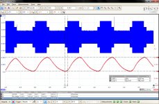
Attached a scope-screenshot of PIN1@AD536 (blue) and PIN24@PIC (red). Input signal 1Vrms/1.2kHz. One can clearly see, at which thresholds the PIC chooses to range up or down. Are the treshold-values ok?
The postfilter: C16 is populated, C13 is not. ok?
Attached a scope-screenshot of PIN1@AD536 (blue) and PIN24@PIC (red). Input signal 1Vrms/1.2kHz. One can clearly see, at which thresholds the PIC chooses to range up or down. Are the treshold-values ok?
The postfilter: C16 is populated, C13 is not. ok?
Attachments
B_C, just for my understanding, it is only with say 1V input? If you turn up or turn down the input level, does it 'move through' the cycling going to a higher or lower att setting?
If you can move through it, it points to a specific resitor or relay, if not it points to a system issue.
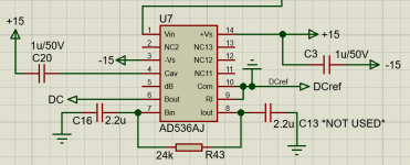
Your last comment about probing the AD536 point to a possible issue with C16 or C20, see attached. Can you verify correct connection, to exclude a PCB trace break somewhere?
Edit: didn't see your last post until now. We had the same thought ;-)
Jan
If you can move through it, it points to a specific resitor or relay, if not it points to a system issue.
Your last comment about probing the AD536 point to a possible issue with C16 or C20, see attached. Can you verify correct connection, to exclude a PCB trace break somewhere?
Edit: didn't see your last post until now. We had the same thought ;-)
Jan
Attachments
Last edited:
B_C, just for my understanding, it is only with say 1V input? If you turn up or turn down the input level, does it 'move through' the cycling going to a higher or lower att setting?
If you can move through it, it points to a specific resitor or relay, if not it points to a system issue.
Actually it is most recognisable and asolutely reproducable at 1,0 Vrms but it happens at all fast transient input level changes -> as long, as I turn the level knob of my generator fast enough it loops at almost any level.
This again points me to the settling time issue. Thanks for the schematic, I'll double check tonight.
Thanks for the schematic, I'll double check tonight.
Seems ok. I could exchange C16 and C20 with new caps, but I am not sure if this really helps since a wrong part-value is very unlikely.
Yes, they are differently.
For instance. Just now I turned the AR on with 0,4634Vrms/1,227kHz at the input and it cycles infinitely between +12dB and 0dB.
Turning up to 1.53Vrms it cycles between -8dB and 0dB.
Another turn on the level knob of my generator gives 2.40Vrms and the AR is still cycling between -12dB and -4dB.
For instance. Just now I turned the AR on with 0,4634Vrms/1,227kHz at the input and it cycles infinitely between +12dB and 0dB.
Turning up to 1.53Vrms it cycles between -8dB and 0dB.
Another turn on the level knob of my generator gives 2.40Vrms and the AR is still cycling between -12dB and -4dB.
Yes, they are differently.
For instance. Just now I turned the AR on with 0,4634Vrms/1,227kHz at the input and it cycles infinitely between +12dB and 0dB.
Turning up to 1.53Vrms it cycles between -8dB and 0dB.
Another turn on the level knob of my generator gives 2.40Vrms and the AR is still cycling between -12dB and -4dB.
Does it finally settle to the correct setting?
B_C,
The only thing I can think of right now is that the averaging cap is not connected at one side.
If you exclude that, I propose you send me the atten board and I check it out here and fix as required. Free of charge of course. Otherwisw we could at this a this Christmas ;-)
Let me know if the cap fixes it, if not I send you my shipping address via PM.
Jan
B_C,
The only thing I can think of right now is that the averaging cap is not connected at one side.
If you exclude that, I propose you send me the atten board and I check it out here and fix as required. Free of charge of course. Otherwisw we could at this a this Christmas ;-)
Let me know if the cap fixes it, if not I send you my shipping address via PM.
Jan
Thanks a lot for the offer. I hope this is not necessary. I am pretty sure now, it must be either the Average-Cap or the Post-Filter. I have some 0805/1206 caps here to test and while the unit is dis-assembled I can double-check the connections of C16 and C20.
Ok, I think the issue is solved now. I just exchanged C16 and C20, doubled-checked all PCB-traces with DMM and populated the display PCB with the original PIC.
The AR now settles astonishingly fast. Since the board was clean and all solder-connections were fine I suspect C20 must have been cracked/damaged.
@Jan: Should I send your PICs back to you (->PM)?
The AR now settles astonishingly fast. Since the board was clean and all solder-connections were fine I suspect C20 must have been cracked/damaged.
@Jan: Should I send your PICs back to you (->PM)?
Amen! When I was selling Quasimodo boards I got a terrified message from a user that his power LED was intermittent. Turns out that he had purchased an LED from Mouser which includes a blinker IC inside the LED package. This fact was recorded in the name of the part on the site, AND on the item description in his Mouser receipt.
Another customer bought a PhaseDots kit, assembled it, and found it didn't work at all. Didn't pass any of the simplest diagnostic tests. I told him to ship it to me for a free repair. The root cause of the problem? Every LED was installed backwards. This occurred even though (a) the very simple schematic was included; (b) the sparsely populated thru-hole board was easy to buzz-out with an ohmmeter on Continuity setting; (c) the silkscreen markings on component side showed the orientation of the LED case's flat spot, and also indicated which hole was for the cathode.
Another customer bought a PhaseDots kit, assembled it, and found it didn't work at all. Didn't pass any of the simplest diagnostic tests. I told him to ship it to me for a free repair. The root cause of the problem? Every LED was installed backwards. This occurred even though (a) the very simple schematic was included; (b) the sparsely populated thru-hole board was easy to buzz-out with an ohmmeter on Continuity setting; (c) the silkscreen markings on component side showed the orientation of the LED case's flat spot, and also indicated which hole was for the cathode.
Capacitors C5 and C17 on the atten board (22pF) can be shorted or correct calibration (-48dB) but we are looking in recommending a new value that makes the adjustment a bit less sensitive.
Capacitors C7 and C11 (22pF) on the atten board can be left out.
Capacitors C6 and C10 (510pF) *may* need to be changed in value, will know in a few days.
Are the changes to the attenuator C5/C17 (shorted) and C7/C11 (unpopulated) still recommended even with the change of value for C6? If so, the BOM does not appear to be updated with these changes.
I will check with Pilgham, they have build more than 10 units now, what their experience is, and I will then update the BOM.
Jan
I have not heard from them, still waiting for mine.
Are the changes to the attenuator C5/C17 (shorted) and C7/C11 (unpopulated) still recommended even with the change of value for C6? If so, the BOM does not appear to be updated with these changes.
OK, Pilgham have assembled 10 units and have done the following:
C7, C11 --> not used
C5, C17 --> changed to 47pF
C6 ---> changed to 363 pF (330+33)
C10 ---> in some units 510pF, in some had to be lowered to 470pF.
Hope this helps,
Jan
- Home
- Design & Build
- Equipment & Tools
- Autoranger for soundcards