I have built one channel only i can't compare without a full setup.
Hi Thimios
could you share pcb layout please pdf or lay file
i am trying to simulate in multisim
if the results are good I want build it.
")
You are fast.Great amplifier I like it
input signal : 707mV 1khz sinus
Output : 26.5 watt max
Thd : 0.002 %
Gain :25.5 dB
Dc offset : <1mV


As commented above, some class A amplifiers have a distinct sound quality. Agreed. Its clear from the specs that many have significant distortion levels that figure in this different sound. JLH's 1969 design is a classic distorter, as are Nelson Pass's DIY class A designs and many other commercial products too.
For all seekers of sound effect amplifiers, the sound quality of the SC/EPE 20W class A amplifier it is dead boring. Read earlier posts here if you think this is just my opinion.
Go ahead, build this Blameless design and and find out what no distortion (well, 0.0006% THD) sounds and indeed should sound like - You will soon be looking for something else like JLH's designs and you can thank their designers for the nice distortion
As commented above, some class A amplifiers have a distinct sound quality. Agreed. Its clear from the specs that many have significant distortion levels that figure in this different sound. JLH's 1969 design is a classic distorter, as are Nelson Pass's DIY class A designs and many other commercial products too.
For all seekers of sound effect amplifiers, the sound quality of the SC/EPE 20W class A amplifier it is dead boring. Read earlier posts here if you think this is just my opinion.
Go ahead, build this Blameless design and and find out what no distortion (well, 0.0006% THD) sounds and indeed should sound like - You will soon be looking for something else like JLH's designs and you can thank their designers for the nice distortion
Thanks Ian
i built f5 last year.
i am still using
very good , sound is warm and detailed
I look for a different sound.
Thanks for advice Ian
Procuro esquema e projeto dele!
Ola, poderia me enviar o projeto deste amplificador amigo? Desde já muito obrigado pela atenção. henrfa@icloud.com
Here are first steps.
Ola, poderia me enviar o projeto deste amplificador amigo? Desde já muito obrigado pela atenção. henrfa@icloud.com

English only please. Rules.
Ola, poderia me enviar o projeto deste amplificador amigo? Desde já muito obrigado pela atenção
Hello, could you send me this amplifier design friend? Since already thank you very much for your attention
As commented above, some class A amplifiers have a distinct sound quality. Agreed. Its clear from the specs that many have significant distortion levels that figure in this different sound. JLH's 1969 design is a classic distorter, as are Nelson Pass's DIY class A designs and many other commercial products too.
For all seekers of sound effect amplifiers, the sound quality of the SC/EPE 20W class A amplifier it is dead boring. Read earlier posts here if you think this is just my opinion.
Go ahead, build this Blameless design and and find out what no distortion (well, 0.0006% THD) sounds and indeed should sound like - You will soon be looking for something else like JLH's designs and you can thank their designers for the nice distortion
I have a JLH headphone amp - is it prone to HD flavoring? I like low (zero if possible) HD too.
JLH's 1969 design is a classic distorter,
Yup - like the SI design, bugger all and less & less as the volume drops.
If you're JLH has "flavour" you've got a problem. (Or your music is compressed to cr*p and you're running the amp @-3db)
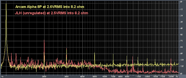
At 70 dB down H2? The point there is how that compares to the less likable sound quality of the Arcam, where the difference you expect with an LTP input stage (H2 cancelleation) begins to show. Let me put my comment in perspective by further quoting from the same article:
BTW, I have both the JLH69 and SC 20 watter and prefer the JLH every time - perhaps more than the 1996 dual rail version. I haven't even considered later reincarnations.
I use the term classic because the descending low order harmonic distortion is a known classic formula for good, sweet and detailed sound - just as Hiraga found, analysed and made even more of in his class A monstres....The JLH second harmonic is quite high (which would lend a rather poor THD score, for what that's worth - not very much) and slightly higher on third harmonic, but aside from a few odd glitches, higher harmonics are pretty much absent....
BTW, I have both the JLH69 and SC 20 watter and prefer the JLH every time - perhaps more than the 1996 dual rail version. I haven't even considered later reincarnations.
I use the term classic because the descending low order harmonic distortion is a known classic formula for good, sweet and detailed sound - just as Hiraga found, analysed and made even more of in his class A monstres.
Fair enough - I think we're in agreement.
I'd like zero distortion (and infinite headroom and...) But If I've got to have distortion, that's how I'll have it, thanks!
(from Tom's Hacks: Class A contender no.1 - JLH 1969)
Yup - like the SI design, bugger all and less & less as the volume drops.
If you're JLH has "flavour" you've got a problem. (Or your music is compressed to cr*p and you're running the amp @-3db)
I looked at the link. The circuit has been changed simply by replacing 2-4 MHz output devices with 30 MHz types.
The SIM it is not for Hood's authentic circuit - which depends on the slower devices for stability. In a metaphorical sense these have a braking effect on the faster preceding signal stages.
Throwing 30 MHz types in their place is like hotting up the engine and using the same amount of accelerator without increasing the stopping power.
The car will run off the road.
As far as Class B amplifiers are concerned 30 MHz devices are good in a sense they work against switching and stored charge effects which slow down the output stage. In effect Class A is an express even with 2 MHz speed and 30 MHz for Class B speed allows a start stop relay trip to be more or less equal in that regard.
Last edited:
We may not need high speed devices for class A but are they really that much of a problem when fitted up with short leads and traces etc? Common low Ft contenders in a plastic case now are MJL21194 and TIP3055, TIP35 but the majority of widely available audio BJTs in modern packages lie in the 30-70 MHz Ft range for class AB use, as said. However, I can't see from my own square wave checks, that it necessarily means they will show instability in class A operation, even if I don't opt for 30+ MHz devices myself.
For the record, as a cheapskate I pick over genuine Chinese product that has a proper manufacturer's datasheet rather than a generic spec. Some is reliably good quality too, such as KTD1047 - KEC's replacement for Sanyo 2SD1047. Ft is a moderate 15 MHz.
KTD1047 pdf, KTD1047 description, KTD1047 datasheets, KTD1047 view ::: ALLDATASHEET :::
We may not need high speed devices for class A but are they really that much of a problem when fitted up with short leads and traces etc? Common low Ft contenders in a plastic case now are MJL21194 and TIP3055, TIP35 but the majority of widely available audio BJTs in modern packages lie in the 30-70 MHz Ft range for class AB use, as said. However, I can't see from my own square wave checks, that it necessarily means they will show instability in class A operation, even if I don't opt for 30+ MHz devices myself.
30 MHz output transistors will increase the open loop bandwidth however the feedback loop will be more susceptible to disruption from delayed signals at higher frequencies and from rf. To reduce the risk the loop gain has to be reduced by some means of compensation - compensation capacitors I see as a worse compromise than using 2 MHz output transistors.
Last edited:
I understand the points you make as I have run afoul of them more than once. However, let's also consider variations to Silicon Chip's 20W amplifier, which is virtually Self's blameless CFP topology.30 MHz output transistors will increase the open loop bandwidth however the feedback loop will be more susceptible to disruption from delayed signals at higher frequencies and from rf. To reduce the risk the loop gain has to be reduced by some means of compensation - compensation capacitors I see as a worse compromise than using 2 MHz output transistors.
This type is often referred to as a "high bias" design as there is little to distinguish it from a class AB design apart from the bias current, feedback resistors and rail voltages. Miller compensation in the VAS at least, usually remains unchanged from class AB to A operation. We can fit 30MHz output devices and whip up the rail voltages and feedback ratio to make a standard blameless amplifier or leave it with +/- 22V rails if we wish to compare apples etc.
So if we are only reducing the supply rails and the gain to suit lower power operation, how will the risk of instability be increased? Will increased output stage bias alone threaten stability or EMR susceptibility?
For other Oz sources of class A designs, ESP offers 2. This is Rod's original design based probably on P3 and using garden variety components with a full 2.6A bias to meet the parallel output pair requirement: 20 Watt Class-A Amplifier
And this is based on a more recent P3a: 25W Class-A Power Amplifier
Both designs are also CFP and not dissimilar to the SC design but the latter uses a single pair of 30MHz output transistors at 1.5A bias, apparently without problems.
Perhaps the use of high Ft devices in class A is not the problem it might present on paper.
I understand the points you make as I have run afoul of them more than once. However, let's also consider variations to Silicon Chip's 20W amplifier, which is virtually Self's blameless CFP topology.
This type is often referred to as a "high bias" design as there is little to distinguish it from a class AB design apart from the bias current, feedback resistors and rail voltages. Miller compensation in the VAS at least, usually remains unchanged from class AB to A operation. We can fit 30MHz output devices and whip up the rail voltages and feedback ratio to make a standard blameless amplifier or leave it with +/- 22V rails if we wish to compare apples etc.
So if we are only reducing the supply rails and the gain to suit lower power operation, how will the risk of instability be increased? Will increased output stage bias alone threaten stability or EMR susceptibility?
For other Oz sources of class A designs, ESP offers 2. This is Rod's original design based probably on P3 and using garden variety components with a full 2.6A bias to meet the parallel output pair requirement: 20 Watt Class-A Amplifier
And this is based on a more recent P3a: 25W Class-A Power Amplifier
Both designs are also CFP and not dissimilar to the SC design but the latter uses a single pair of 30MHz output transistors at 1.5A bias, apparently without problems.
Perhaps the use of high Ft devices in class A is not the problem it might present on paper.
I looked at the P3 amplifier on Rod Elliott's site it is interesting he had this to say:
"Update - 25 June 2009 - Although the last update highly recommended the latest OnSemi power and driver transistors, they remain hard to get in most countries. As a result, the recommended power transistors are now the much more readily available MJL21193/4. While in theory these are not quite as good as the latest versions, they are still excellent devices. It is extremely doubtful that anyone would ever pick any difference with test instruments, and there will be no change that is audible."
The distortion spec for the P3 and P3A is the same. That may be a case of being modest however these are less good than the Silicon Chip 20 watt Class A and given a choice I would opt for the latter.
CFP output stages are regarded as better by some authors - Otala and Linsley-Hood among them. The latter did a comparison of various output stages without negative feedback into 10R at 20 kHZ with bias current of 60 m.a. The results for CFP were 1.15 % against the Darlington 2 %.
Other factors to take into account are that there is only one forward biased emitter diode in the driver of a CFP and two in a Darlington which complicates stabilising the standing current.
Also the feedback around the CFP tends to reject the intrusion of spurious signals reflected into the output.
Looking at specification sheets for MJL21193/21194 there is an additional table showing that as an emitter follower the distortion for this device without negative feedback is less than 1% into 8R at 20 kHz. Some contributors to other threads rate these devices highly for linearity.
The closed loop gain for the Silicon Chip Class A amplifier is 20.6 whereas the Ultra LD High Power amplifier has 24.5. These gain levels are fairly typical of what might be required for driving them from a digital source via a simple volume control. I would leave well enough alone.
Before going too much into stability issues, have you read the article on this subject by Nicholas Vinen in the July 2011 issue of Silicon Chip.
I scanned the article and posted pdf attachments probably in January or February last - I cannot trace the link now so possibly it has been removed.
I don't want to try to put this in my own words the pictures give a better explanation.
- Home
- Amplifiers
- Solid State
- Aussies - Silicon Chip 20W Class A Amplifier opinions?