Peter, need your help.
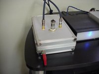
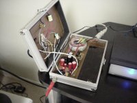
I have eventually finished my LM4780 in parallel configuration. When I powered it up and measured DC at the output, I am getting approx negative 150mV on both side. Initially, when I attached a speaker, I found that the right channel was very much softer than the left, and after a few minutes, there was no more sound from the right channel.
What is your diagnosis of these symptoms, and what are things that I should check for?
One other thing is that when I touch the chassis of the amp, there is a slight hum, and when I lift my hand off it, it goes away. I have not used any grounding for the amp. The side panels, front and back are aluminum and the base is wood. Have not made the cover yet.
BTW, my pre has no DC on the output.
Thanks, Peter.
You may have grounding problem. When I tried to run two LM4780 boards configured in parallel I had substantial hum noise ( that was not happening with LM3875 in a same setup). I got rid of ground problems by simiplifying power ground connections. It was described here: http://www.diyaudio.com/forums/showthread.php?postid=787773#post787773
Now, LM4780 especially configured in parallel, has quite substantial DC offset. The readings you are getting are not way off, but rather on a higher side. Last year I was thinking about using the chips in parallel mode so I measured 100 of them for offset (configured in parallel mode). The lowest reading I was getting was about 80-90mV and as high as 170mV. This was with about 15k input impedance (50k pot in parallel with 22k input resistor). Now, if you use the chips in power amp, you will have preamp connected to the amp with usualy low output impedance. In that case that impedance is in parallel with amp's input impedance and lowers the offset substantially (that will not apply though if your preamp is AC coupled, and it seems like yours is).
The solution would be trying different chips, preferably sorted for low offset, or using a capacitor between R3, R5 and ground (22-47u should be fine). You may try to lower value of input shunt resistor (R4) by half.
DAC
Peter,
I took one of my All-In-Ones to a HeadFi meet in San Jose, and it was very well recieved by those who auditioned it.
We A/B compared it using a Rotel RCC-1055 as the source against its on-board DAC, and using a Millett Hybrid Head Amp and several different headphones. You may pick up a few orders as a result.
I was wondering if you ever considered stacking the TDA1543s as a possible means of reducing conversion errors? Could this work.....and could the board supply enough current for 2 or 3 chips. Would other components require different values to accommodate such an experiment?
Is this a dumb idea?
Robert
If you stack TDA1543 chips, the I/V resistors values will need to be changed. IIRC, the first Kusunoki DAC was using 4 chips in parallel and all 3 resistors were 1k (with 9V supply). I've built that DAC, but preferred a single chip version. Four chips in parallel had more slamm, but were lacking refinement, immediacy and delicacy of the sound, the virtues I value much more.
Occasionally, I compare my modified NOS DAC to my unmodified ML360S DAC, the NOS is always preferred")
Occasionally, I compare my modified NOS DAC to my unmodified ML360S DAC, the NOS is always preferred
At that time I was using a different regulator: http://www.diyaudio.com/forums/showthread.php?postid=166988#post166988
AN8008 would not last feeding 4 chips in parallel.
AN8008 would not last feeding 4 chips in parallel.
here ya are peter. i added a little glass to the dac.
its kinda like the decware zbox. but with only one source the dac
dac sounds the same just a little more base. and it runs on a batterys so there no humm.
its funny all the resisters i used on it are leftovers from my lm4780
kit
i need to add a ac plug and a relay for charging the battery
and its finished
cheers.
Attachments
RF noise in my interated
to everyone:
i build an integrated amp, based on Peter's SE kit. Have two 1500mF on rectifier board and two 100mF MKPs per each amp channel.
I experience quite anoying amount of RF noise comming to the speakers. The power grounds should be OK (ground star with 10ohm rezistor)
....maybe the wires from big caps?
also, it seems to be influenced by the level of attenuation...
have anyone some idea, how solve the problem?
When the volume is completely down, the RF is most significant. Yestarday, I changed the stepped attenuator for Nobel pot, but nothing changed....
I had idea, that the cap wires might be too long (around 2 inch). Could it act as an antenna? Or is it rather on the signal path side?
I had idea, that the cap wires might be too long (around 2 inch). Could it act as an antenna? Or is it rather on the signal path side?
- Status
- This old topic is closed. If you want to reopen this topic, contact a moderator using the "Report Post" button.
- Home
- More Vendors...
- Audio Sector
- AudioSector-chip amp kits, dacs, chassis