Well it is the same as my paypal.
I still have the NX HI-Q I discovered, to do...
I found the orientation of the BG N info on the board, but only after you mentioned it. It would take me a month to go through all your posts Peter! You have been around this board for awhile. The circuit seemed more than simple enough at first look so I just dove in. I think everything but the BG N orientation went well.
I have no idea what it is but I can hardly get solder to suck up off of the stuff though. The PCB and metal are just different than some other stuff I solder on where I get cleaner open holes. I am sure I could use a better solder sucker but still, if I ever find out I need to make more changes this is all going to become point to point or buy all new stuff (not possible). It has been an educational experience. A lot of it has gone into messing with my ADCOM GCD-575 I got for free (1541a chip in it). I am considering using it for a transport but the Shigaclone or whatever looks fun if I could get ahold of the pieces.
It may be harder with my boards to desolder components, as I use minimum diameter holes, which are also through plated. It's best to use solder wick, and if that does not work, clear the hole with stainless pick first: http://www.hartvilletool.com/product/11679
If you mean shields on signal wires, I don't use them, and I'm not crazy about all metal enclosures either.
If you mean shields on signal wires, I don't use them, and I'm not crazy about all metal enclosures either.
I've had pretty good results on Peters (DAC) board using a solder wick. To be honest, I've found that solder suckers are really only good on bigger areas like around say the transformer connections etc. Wicks work best on the smaller holes. Heres another tip - when you get the component out, use another bit of wick to clean the hole again. As Peter says, the holes are only the right size and its quite easy to force a component lead through and lift the pad on the far side.
I too installed the BG the wrong way around - but Peter had told me and I forgot about it until it was too late. The DAC is very well worth it though, one of the best that I've heard....
Fran
I too installed the BG the wrong way around - but Peter had told me and I forgot about it until it was too late. The DAC is very well worth it though, one of the best that I've heard....
Fran
I meant shields on the chips.
I will have to find my whick or get some more or well something...
I think the PCB choices are good, but the old heat one side, pull a little, heat the other, pull a little, gets to you and runs the risk of popping off the pad. On C8 I think it is the PCB coating on the lead to the three prong whatever it is that looks like a JFET (do not remember part name) kind of dissappeared a little so there is solder on the tracing now that will not ever come off. C8 is wired across ground and input or output, whatever one it is suppose to be, so the cap faces straight down, and then C10 streches to it now (barely).
I am afraid of the BG NX HI-Q though, risky business. If I am not mistaken I would have to solder to the big chip if it did not come out right.
Do you use the stainless pick heatd up or?
I tried copper shielding on chips, it could improve things a bit, but if anything, it was so subtle that I wouldn't care much about it.
To remove caps, it's best to use 2 soldering irons, heating both pins at the same time, but you need another person to help ( I use my kids")
Then use solder wick to clear the hole (iron temp approx 800 deg F). Some holes will be stubborn, especially those on ground plane, here I use stainless pick (a needle is good too) and while heating the pad, puncture the solder in the hole clearing it out this way, solder wick for final clean up.
A small BG NX (0.47uF) is not that critical and I wouldn't be touching it if it's installed opposite way.
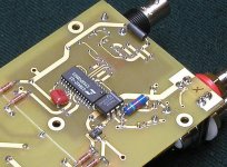
Picture below shows how C10 mounts (it's Wima now which is better than previously used Panasonic)
To remove caps, it's best to use 2 soldering irons, heating both pins at the same time, but you need another person to help ( I use my kids
Then use solder wick to clear the hole (iron temp approx 800 deg F). Some holes will be stubborn, especially those on ground plane, here I use stainless pick (a needle is good too) and while heating the pad, puncture the solder in the hole clearing it out this way, solder wick for final clean up.
A small BG NX (0.47uF) is not that critical and I wouldn't be touching it if it's installed opposite way.
Picture below shows how C10 mounts (it's Wima now which is better than previously used Panasonic)
Attachments
I will have to take a picture later. My C8 (I think, long slender BG N that was on top and C10 mounts to the lead of) if on the bottom now, across the little switcher, and C10 on the lead to ground, and on I think the resistor? Not sure where the other lead went too.
I might have to get a SS pick, looks handy.
I might have to get a SS pick, looks handy.
Hey Peter I was reading back on your expermints with Rubycon capacitors...
I have an idea I might try with my BG 1000uf STD since you think they do not sound as good as the 100/100uf combo... This stems from an expermint with speakers, basket, and crossover.
If you are adventuruss and see no reason not to try this...
Ground the capacitor case to your star ground on the Rubycon Z's, or any capacitor that is signal especially that you find to be harsh. I think a wire with rubberband, no soldering, anything, will be sufficient.
I might try this along with removing the plastic since I have no desire to ever change the 100uf BG output caps. The STDs are fine and I can mark the negative side if I ever take them out.
Hi,
in most electrolytics the can is physically isolated from the capacitor.
However there is some leakage from the -ve terminal to the can that may raise the can voltage towards the -ve potential.
Now, how do we make a corrosion resistant connection between an aluminium can and the various plain / tinned / tin plated / silver plated copper wire?
I checked to make sure that the can was not actually connected to either side. I guess this might be the case with some capacitors, as maybe not all are isolated.
Corrosian resistant... not sure... I do suspect that just wire touching it however will take a very long time to show anything especially and extremely low levels of discharge.
Peter when did you find high voltage on the can? Perhaps it depends on the size of the can too?
Corrosian resistant... not sure... I do suspect that just wire touching it however will take a very long time to show anything especially and extremely low levels of discharge.
Peter when did you find high voltage on the can? Perhaps it depends on the size of the can too?
Destroyer OS. said:Peter when did you find high voltage on the can? Perhaps it depends on the size of the can too?
I just checked yesteday and in my amp BG N 100/50 has 1V potential (in positive rail) and -31V in negative rail. I recall someone before was reporting that too.
Now here is something I can not test... What is the amperage? The voltage may be completely unimportant if the amperage hardly exists.
I do not have any fancy equipment for measuring amps .
I think it is important to realize this connection only happens to exists when the amp is on, when it is off it will not even read on instruments, at most you get a small twitch, almost to faint to see, on an analog meter. This makes me think the amps are so low that the actual power on the can is in no way an issue to ground clamp, solder, or light touching.
I do not have any fancy equipment for measuring amps
.I think it is important to realize this connection only happens to exists when the amp is on, when it is off it will not even read on instruments, at most you get a small twitch, almost to faint to see, on an analog meter. This makes me think the amps are so low that the actual power on the can is in no way an issue to ground clamp, solder, or light touching.
- Status
- This old topic is closed. If you want to reopen this topic, contact a moderator using the "Report Post" button.
- Home
- More Vendors...
- Audio Sector
- AudioSector-chip amp kits, dacs, chassis