
That is a thing of beauty!!
Can you post some close up pictures? It really does look like a work of art.
I use his USB DAC with silver interconnects, so I know the sound is wonderful.
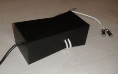
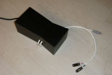
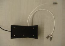
neil_kaye said:I have been working on this for a while:
Peter's NOS DAC housed in a CNC milled aluminum chassis (milled from a single billet) with pure silver digital and RCA out wires.
It sounds fantastic.
Can you post some close up pictures? It really does look like a work of art.
I use his USB DAC with silver interconnects, so I know the sound is wonderful.
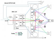
Chi Ming said:Im a little confused... Does anyone have schematic or pictures of the connection using dual supply transformer to the 2 rectifier board and to the 2 amplifier board.
Thx!!!
Ming,
A single transformer with dual secondaries will create the V+ and the V- for a single rectifier board. The V+ out and V- out go to the V+ and V- in on the amplifier board.
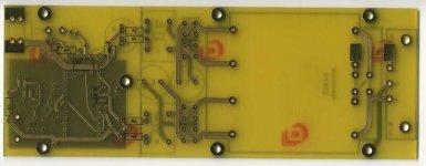
Hi Peter: I am presently fabricating an enclosure for my gold PCB DAC. While laying out and drilling holes, my hole pattern (in my gold DAC PCB) does not match your hole pattern info above.
The PCB is 187mm x 68mm, and the first set of holes are 18 mm from the front edge, but the 94mm and 170.5mm dims seem incorrect. My center holes are more like 97mm from the front edge, and the rear holes are approx 165 mm from the front edge. I have 6" calipers so the last # is a little +/-.
The 61mm width spacing appears correct.
Do the 97mm and 165 mm dims look at-all familiar?
The impedance is 22k and it can be raised slightly, however going much over it is not recommended as the DC offset increases substantially.
If you already have the PCB why not use it as template to drill the holes? That's what I always do.
The previous board version, with through hole CS8412 chip has a different hole spacing, but that board was discontinued at least two years ago and I didn't expected that's what you have. The other two holes are indeed 94 and 165.5mm from the front edge.
boywonder said:Hi Peter: I am presently fabricating an enclosure for my gold PCB DAC. While laying out and drilling holes, my hole pattern (in my gold DAC PCB) does not match your hole pattern info above.
The PCB is 187mm x 68mm, and the first set of holes are 18 mm from the front edge, but the 94mm and 170.5mm dims seem incorrect. My center holes are more like 97mm from the front edge, and the rear holes are approx 165 mm from the front edge. I have 6" calipers so the last # is a little +/-.
The 61mm width spacing appears correct.
Do the 97mm and 165 mm dims look at-all familiar?
If you already have the PCB why not use it as template to drill the holes? That's what I always do.
The previous board version, with through hole CS8412 chip has a different hole spacing, but that board was discontinued at least two years ago and I didn't expected that's what you have. The other two holes are indeed 94 and 165.5mm from the front edge.
Attachments
neil_kaye said:I have been working on this for a while:
Peter's NOS DAC housed in a CNC milled aluminum chassis (milled from a single billet) with pure silver digital and RCA out wires.
It sounds fantastic.
Nicely done, looks like bigger brother of Progression DAC
")
Attachments
Peter Daniel said:
If you already have the PCB why not use it as template to drill the holes? That's what I always do.
The previous board version, with through hole CS8412 chip has a different hole spacing, but that board was discontinued at least two years ago and I didn't expected that's what you have. The other two holes are indeed 94 and 165.5mm from the front edge.
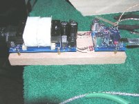
I apparently have the older gold DAC pcb with the DAC chip on the bottom....I ended up using a transfer punch to get the hole pattern on my aluminum base, but the board is a little wobbly/inaccurate due to the components on the bottom. The hole pattern came out fine, though.
Since I have a plotter at work, I prefer to layout the hole patterns in SolidWorks and plot a paper template, fast and accurate.
I'll post pics when the enclosure is completed.
Peter Daniel said:You may also try to remove the sleeves from the caps, especially the output coupling caps.
And these advices hold for the caps in your phono amp too, Peter? Could you please tell me how to do this when the caps are mounted, so that I don't ruin this beatiful phono amp?
Best wishes from
Jan Ove Tangen
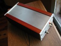
I finished the DAC enclosure, thanks Peter and everyone else on this thread for hints, tips and ideas.
The wood is laquered african mahogany, top and end caps are aluminum sanded with 120 grit paper then aluma-dyne 2300 and 2310.
The wood sides have brass threaded inserts in the ends to accept the button head screws, and there are black chrome small cone tips for feet.
I used a panel mount IEC power inlet for easier mounting, since you don't have to line up as many parts when machining the cutout compared to the PCB mounted power inlet.
see pic
Attachments
That looks great 
Yes, you can try it with a phono as well.
Use a blade and run it down the sleeve, but make sure it's not too deep so it scratches aluminum. And then just tear it off.
tangen said:And these advices hold for the caps in your phono amp too, Peter? Could you please tell me how to do this when the caps are mounted, so that I don't ruin this beatiful phono amp?
Yes, you can try it with a phono as well.
Use a blade and run it down the sleeve, but make sure it's not too deep so it scratches aluminum. And then just tear it off.
New DAC build
I have about 20 hrs on my recently cobbled together USB DAC and am SO pleased. Peter, your layout is beautiful and the sound equally so.
I have mated this guy with a pair of LM3875 GC amps and want to impedance match these two for direct connection - no preamp. The volume control I have on the amp input seems to ruin the sound at anything less than wide open, SOO...
Peter, what is the recommendation for direct connection of the USB DAC to the LM3875 GC so that each sees the best load?
Attachments

- Status
- This old topic is closed. If you want to reopen this topic, contact a moderator using the "Report Post" button.
- Home
- More Vendors...
- Audio Sector
- AudioSector-chip amp kits, dacs, chassis