Ceramic capacitors exhibits mostly pathological behavior, and ferroelectric effect, piezoelectric effect and electrostriction make me left them aside into my calculations, just for simplicity.
High-K ceramics like X7R etc have horrible capacitance variation versus voltage and temperature, also very high microphony. Not a problem at all for decoupling power supplies, but they should never used as filter or signal coupling caps. Also the microphony is a big problem for decoupling high impedance nodes (like LDO VREF), since vibration translates to delta-charge, that means current, and the resulting voltage is proportional to the impedance the capacitor sees.
Low-K ceramics like NP0 on the other hand are close to perfect : negligible capacitance variation, very stable, extremely low distortion, low inductance, zero microphonic/piezo effects, etc. Due to the low inductance SMD NP0 is really the only choice for a filter designed to get rid of HF interference, like amp input lowpass filter, DAC IV, etc.
Class 1 ceramic capacitors (AKA C0G, AKA NP0) are far to be perfect, they have the lowest piezoelectric effect and the lowest TCC (temperature coefficient of capacitance), however all ceramic capacitors exhibit piezoelectric effect at some degree, NP0 special formulations, its geometry, and very small sizes make them quite immune to microphonics.
Considered as paraelectric, its tan (δ) is comparable with those of polymer films, but its permittivity is at least one order of magnitude higher, then linearity
b/a ≈ [∣ε(ω)∣ tan (δ)] / ω
Will be about one order of magnitude worse, hence not so extremely low distortion.
I'd be interested in manufacturer specs of this, it seems noone ever gives distortion, dC/dV or microphony specs on capacitor datasheets !
:
Are you sure ajout NP0 being piezo ? Kemet says : "Note that there are no measurable piezoelectric effects in Class 1 capacitors, such as C0G or NP0"
:
Are you sure ajout NP0 being piezo ? Kemet says : "Note that there are no measurable piezoelectric effects in Class 1 capacitors, such as C0G or NP0"
Are the form factor is important for signal path with a NPO: e.g. smd 0603 or littlier if uou can soldered it ? the littliest the best inductance ?
But some seems prefer PPS caps for digital signal coupling e.g. or Mica smd when the value is low ??????
In Power // decoupling for digital what is the best choice between a 805 case 1 uF or a max 0.1 uf NPO 0603 case ?? Or in the same idea a bigger 1205 smd acrylic cap with X7R specs but no piezzo effects ?
many automotive engineer here says if X7R is good enough for industry it's good enough for audio ?
For lowest inductance choose the smallest package you can handle/assemble.
I can with great difficulty work with 403 caps. I have a few hundred of them. All NP0/C0G
I recently described attaching one as the first stage RF attenuator to the back of the RCA input socket.
Once you have your package determined, H.Ott tells us to find the highest capacitance in that package.
I can with great difficulty work with 403 caps. I have a few hundred of them. All NP0/C0G
I recently described attaching one as the first stage RF attenuator to the back of the RCA input socket.
Once you have your package determined, H.Ott tells us to find the highest capacitance in that package.
Are the form factor is important for signal path with a NPO: e.g. smd 0603 or littlier if uou can soldered it ? the littliest the best inductance ?
If it is a coupling cap at audio frequencies, inductance (ESL) doesn't really matter (unless you parallel it with other caps). Even a very large capacitor will have low enough inductance to make the effect negligible at 20kHz.
If you want to get rid of cellphone interference by putting a lowpass filter at the input of your gear, then you want something that still looks like a lowpass at 2GHz. In this case all parameters are reversed : the value of the capacitor doesn't really matter, only its inductance does. And the value of the resistor matters much less than the parasitic capacitance across it. So you want a resistor that is not too small, with good HF properties, or maybe a ferrite bead (watch out for distortion), and a capacitor that is very small, like a SMD film or C0G ceramic. Of course, the inductance of the "GND" matters...
In Power // decoupling for digital what is the best choice between a 805 case 1 uF or a max 0.1 uf NPO 0603 case ?? Or in the same idea a bigger 1205 smd acrylic cap with X7R specs but no piezzo effects ?
For decoupling digital supplies, the inductance and ESR of the capacitor matter a lot more than its value.
The inductance depends mostly on package size. Of course smaller is better, but at some point (below 0805) mounting inductance dominates. So, unless you use really close coupled power planes close to the surface, something extremely annoying like 0402 will give you very little benefit over easy to handle 0805...
The ESR matters a lot, because if it is too low, or the ESL too high, paralleled caps will create a LC resonance with not enough damping, and it will ring.
This means that 2x1µF 0805 in parallel will have better performance than 1µF // 100nF... same inductance, more capacitance, less ringing.
The 100nF caps are used in two cases :
1- old habits die hard
2- the board has a huge FPGA or CPU and what matters is inductance of the decoupling network, in this case you will see a hundred very small caps in parallel.
I don't use NP0 for power supply decoupling because the values are way too small.
many automotive engineer here says if X7R is good enough for industry it's good enough for audio ?
X7R is good for decoupling.
Microsoft had too issue an app note for cellphone makers, highlighting the fact that using X7R (or worse) as signal coupling caps, or DC-blocking caps on the headphone output, will make it impossible for your product to get some MS-certification (I don't remember which) because the THD numbers get so bad as to fail the THD test in the certification... which is far from hifi...
I'd be interested in manufacturer specs of this, it seems noone ever gives distortion, dC/dV or microphony specs on capacitor datasheets !
Most capacitor manufacturers give relevant data for linearity, i.e. tan (δ) and/or ESR and permittivity.
dC/dV is mostly negligible, except perhaps for Class 2 and Class 3 ceramic capacitors, and on this case they give that parameter as capacitance change vs. applied voltage curves, on this post a link IIRC
http://www.diyaudio.com/forums/lounge/139014-audiophiler-capacitors-ebay-10.html#post3991497
Piezoelectric effect is complex enough to hide it under the carpet, note that PTFE capacitors are quite microphonic because PTFE is quite piezoelectric.
Are you sure ajout NP0 being piezo ? Kemet says : "Note that there are no measurable piezoelectric effects in Class 1 capacitors, such as C0G or NP0"
Mike Turner from Kemet says
sic "All ceramic caps exhibit some form of piezoelectric effect."
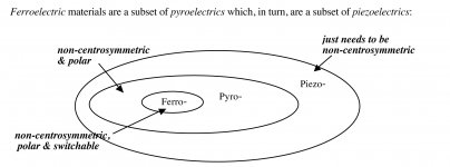
IMHO. The symmetry requirements for zero piezoelectric effect are huge, and of the 32 crystal classes, 21 are non-centrosymmetric.
Marketing strategies, manufacturers want to sell billions of caps, sometimes they lie.
My personal experience with NP0 caps was horrible, several days to find a failure in a TV, an SMD cap that became very microphonic, although it was under specs measured with the capacimeter, into the circuit it failed, I really hate them.
Ah, BTW, I was wrong, NP0/C0G are a subset of Class 1 capacitors, you are right, my apologies.
Attachments
Last edited:
Once you have your package determined, H.Ott tells us to find the highest capacitance in that package.
I mean because the lower ESR... and if only values are not involved in frequency filtering
") (filter I mean).
(filter I mean).My short experience is I can't hear in digital decoupling difference with inductance but the greater capacitance in digital power decoupling give me each time the best sonic result.
My understanding is just 0.1 Cog/NPO should be used to // this bigger cap.
But some here says that a 1 Uf 0805 X7R is good enough ! But the scope, is someone able to hear the difference or is it just advised to put Cog to avoid worser piezo the pcb get older like in the same time the piezzo effect involved even with new solderrings ?
What is the best trade off between inductance, dielectric & piezzo ?
In digital design some tends to prefer for sound: smd PPS, acrylic in 1210 case, at least Tantalum for its particular damping aspect in some place.
Not involving the cost production but just DIY and best trade offs : what about smd parts in amps ?
Good for bypass use
I have used the Audiophilers as well. They came out about 3 years ago at some of the common supply houses. I found they did not sound nearly as nice as any other polys I had. This includes things like the Jantzen crosscaps and Solens. If find they do work OK for bypassing large electrolytic capacitors in tube amp power supplies though.
I have used the Audiophilers as well. They came out about 3 years ago at some of the common supply houses. I found they did not sound nearly as nice as any other polys I had. This includes things like the Jantzen crosscaps and Solens. If find they do work OK for bypassing large electrolytic capacitors in tube amp power supplies though.
PTFE is piezoelectric?
It's heeeeeere!
Morgan Jones - Valve Amplifiers 4th Edition - Page 256
When people post wrong stuff, yes, it matters.
I bought the book following your advice, and now you tell me that it is wrong?
Next time, please, read the book before make publicity.
(note the acknowledgements...).
Maybe you didn't insults him enough, or maybe he is right and PTFE is piezoelectric.Acknowledgements
.
.
.
Thermionic design cannot proceed in a vacuum, so the author is grateful
for the perceptive insights and insults freely offered by Stuart Yaniger over
the recent years.
.
.
.
Piezoelectric Effect in Teflon Cable
http://iopscience.iop.org/0022-3727/35/6/301/pdf/0022-3727_35_6_301.pdf
New materials with piezoelectric properties - ResearchGate
- Status
- This old topic is closed. If you want to reopen this topic, contact a moderator using the "Report Post" button.
- Home
- Member Areas
- The Lounge
- Audiophiler capacitors on ebay