Hi Doug,
Edmond told me that he believed the arrangement used in TMC was from Baxandall. I believe that Baxandall did not publish it and probably regarded it only as a curiosity, and perhaps did not relize the power of the technique when properly applied...
Not wishing to nit-pick here, but I genuinely am interested in how the idea has developed. Peter Baxandall never, to my knowledge, published anything on it, and as far as I know his letter to me in 1994 was all he ever wrote. (The full letter has now been published in book form by Jan Didden, of course) So I am unclear as to how Edmond came across the idea. You know him better than I do; perhaps you could ask him.
I feel sure that Peter did appreciate the power of the technique.
BTW, the origins of TPC are interesting as well. In the early to mid 70's at Bell Labs we called it "T" compensation. Two of my collegues, Jimmy Tow and Lee Thomas, of BIQUAD fame, recognized that they needed op amps with higher in-band open-loop gain to make active filters with the performance we needed. In response, the organization I was in at the time (not me, I was working on IC PLLs) designed IC op amps with T compensation. They were then used all over the place in the Bell System. To the best of my knowledge, T compensation (TPC) was first developed at Bell Labs, probably circa 1973.
This is a bit of history worth recording.
Inclusive compensation , that is enclosing the output stage in the miller
loop , has been made in the 60s in commercial designs , as in the Gundig
schematic i posted two pages ago , so it s unlikely that Baxandall own any
credit in its invention/use.
As for TMC , it has been patented by Hitachi in the 70s but it has gone unknown
untill Edmond Stuart popularized it in this forum.
I think that I can answer this question, since I have been doing it of late.The simple cheap way is to make a small auxiliary PS, using a small filament transformer, such as Triad VPP10-250 from Digi-key. It is:
TRANSF 5VAC .5A 2.5VA WORLD SERIES
and a LDO for 3.3V logic. You could sub a cheap DC/DC for this to reduce power even more.
I have not done a lot of work on this issue, but I do not think it is as simple as you suggest. You need a transformer with a low magnetising current, and these tend to be expensive, due to the high inductance required.
I think that I can answer this question, since I have been doing it of late.The simple cheap way is to make a small auxiliary PS, using a small filament transformer, such as Triad VPP10-250 from Digi-key. It is:
TRANSF 5VAC .5A 2.5VA WORLD SERIES
and a LDO for 3.3V logic. You could sub a cheap DC/DC for this to reduce power even more.
The 3.3V logic does not use much power in standby, so ckts can be put to sleep and only the wake up logic needs to be active.
Use a relay such as Panasonic ALE1PB05 to switch on the main PS. I looked at Triacs but they are lossy at high currents. Relays are reliable enough for this application.
The expensive way is a off-line switch mode PS for the auxiliary 3.3V
Yet another option, Fairchild FSAR001BNY
Rick
Small 2W SMPS are down at 20mW no load power routinely now, driven by the dictates of the consumer industry (ESP. Japanese). However, since this is DIY, and especially because I for one am interested only in the high end, I have no compunction using a 3VA transformer for the standby circuitry - it's powered up continuously although the MCU'S of course is in sleep mode. Standby power is typically about 100mW to 200mW on my designs.
Hi Doug
Enjoyed the books and the Wireless/Electronics articles!
I would love to see the next book be a different volume rather than a different edition. I don't want to pay again for all the info I already have. I think it is safe enough to assume that most readers will have a previous edition.
A look at alternate compensation schemes would be great, for example, those used in Bryston amps. I appreciate that an infinite realm still lies within Lin, but there are other topologies that have performance beyond any Lin circuit you've shown or that I've seen elsewhere.
As others have suggested, more about current-feedback designs would be of interest. Their "tradition" of not being as linear as voltage-FB circuits is fast becoming obsolete, and at the extremes of performance for both (using low-THD as the guide) the lines between the methods are getting blurred.
Anyway, always look forward to your observations and unique presentation.
PS: Hey Bob, TMC was used by Leach (but not called that) in the 1978 or so version of his low-TIM amp.
Kevin O'Connor
Last edited:
Hi Doug
Enjoyed the books and the Wireless/Electronics articles!
I would love to see the next book be a different volume rather than a different edition. I don't want to pay again for all the info I already have. I think it is safe enough to assume that most readers will have a previous edition.
That is just not the way that new editions of books work. It is never assumed that purchasers have previous editions. The general rule in the business is that a new edition should have not less than 10% new material, plus of course clearing up any previous errors. I am planning about 50% new material. I hope you think that's enough.
There will be a great deal on this.A look at alternate compensation schemes would be great,.
Not sure what you mean here. Got schematic?for example, those used in Bryston amps.
Are there? The new book will include a detailed study of many topologies, and I have to tell you that every one I tried had snags not shown by the Blameless configuration.I appreciate that an infinite realm still lies within Lin, but there are other topologies that have performance beyond any Lin circuit you've shown or that I've seen elsewhere.
[/QUOTE]
They are certainly not identical. The two methods do quite different things in quite different ways. I'd be interested in a link to wherever it is that someone claims to have proved they are the same. Should be amusing...
Sorry if my holiday delayed your amusement, but here is the link to the post in
http://www.diyaudio.com/forums/solid-state/171159-bob-cordells-power-amplifier-book-122.html#post2414320
I have subsequently done my own analysis that assumes less and is actually simpler. I find that the two methods achieve quite similar results in quite similar ways, but they are not identical. I think the comparison is instructive and plan to write it up. I can send you a draft if you are interested.
Best wishes
David
Here is the original quote and the reply from Bob Cordell. It does not agree at all with the just stated conclusions, taken very much out of context.
Quote:
Originally Posted by michaelkiwanuka
At last someone who knows what he's talking about!
What i have discovered so far is some folks lack of knowhow when it comes to implementing TPC which has led to patently false comparisons with TMC.
The same folks have failed to appreciate that TMC is related to TPC more closely than they accept, and that TMC is a poor relative of TPC.
Hi Mike,
Yes, megajocke certainly knows what he is talking about, and his results are impressive and insightful. It is indeed useful that he has shown that the addition of an appropriate lead network in the feedback path can make TPC act similarly to TMC.
However, this certainly does not mean that the others here have a lack of knowhow, and you are insulting them by suggesting that. Moreover, I say once again, TMC is equal to or better than TPC and at the same time it does not require a lead circuit in the feedback path to make it so.
This may be a subjective matter, but I do not agree with your conclusion that TPC and TMC are closely related; they are not.
Finally, all of the evidence so far indicates that TMC is certainly not a "poor relative" of TMC. I consider it to be superior to TPC, and so do Baxandall and Self. You are on the wrong side of the fence on this one and are just being stubborn about it.
Cheers,
Bob
Any topology you pick will have tradeoffs - none offer an overall solution in my view where you don't have to relax requirements somewhere. It's just a matter of where you set your priorities I believe.
The blameless is simple and achieves remarkably good performance, of that there is no doubt.
The blameless is simple and achieves remarkably good performance, of that there is no doubt.
I do hope any discussion of TMC would involve understanding the issues, megajocke, Syn08 analysis
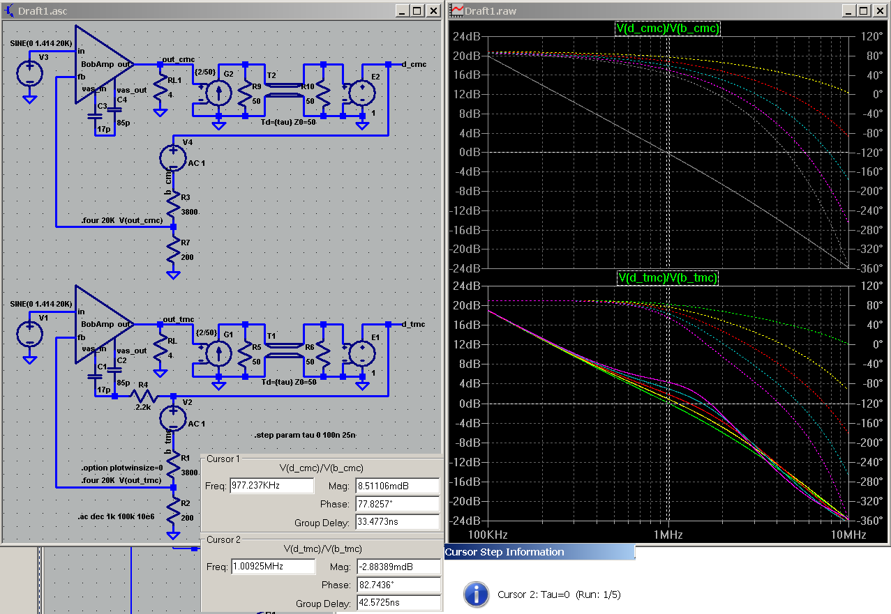
I also hope my sims make it clear that the nesting of the feedback gives a "unexpected" stability picture - the "single pole" apperance of the Global loop is really hiding complexity:
http://www.diyaudio.com/forums/soli...lls-power-amplifier-book-134.html#post2420438
I also didn't fully agree with Bob's assertion later in the thread that nonlinear stability/clipping recovery was "superior" with TMC - I would want explore it more, need to see more evidence
but this would be a step up in level/depth presentation from Self's earlier book editions, if not in his own understanding
Last edited:
Here is the original quote and the reply from Bob Cordell. It does not agree at all with the just stated conclusions, taken very much out of context.
Quote:
Originally Posted by michaelkiwanuka
At last someone who knows what he's talking about!
What i have discovered so far is some folks lack of knowhow when it comes to implementing TPC which has led to patently false comparisons with TMC.
The same folks have failed to appreciate that TMC is related to TPC more closely than they accept, and that TMC is a poor relative of TPC.
Hi Mike,
Yes, megajocke certainly knows what he is talking about, and his results are impressive and insightful. It is indeed useful that he has shown that the addition of an appropriate lead network in the feedback path can make TPC act similarly to TMC.
However, this certainly does not mean that the others here have a lack of knowhow, and you are insulting them by suggesting that. Moreover, I say once again, TMC is equal to or better than TPC and at the same time it does not require a lead circuit in the feedback path to make it so.
This may be a subjective matter, but I do not agree with your conclusion that TPC and TMC are closely related; they are not.
Finally, all of the evidence so far indicates that TMC is certainly not a "poor relative" of TMC. I consider it to be superior to TPC, and so do Baxandall and Self. You are on the wrong side of the fence on this one and are just being stubborn about it.
Cheers,
Bob
I long ago despaired of Bob's and Edmond's obstinate refusal to recognise that "TMC" is simply TPC applied about the transimpedance stage and the output stage with the input stage subjected to a single pole global feedback rolloff.
This is very simply demonstrated by merely examinng the minor loop gain to which the last two stages of a "TMC" compensated amplifier are subjected.
One should then find (provided the compensator component values are identical for valid comparison) that the total loop gain to which the last the second stage and the output stage of a "TMC" compensated amplifier is virtually identical in magnitude of the major loop gain of a TPC compensated amplifier. This suggests that a more descriptive name for "TMC" is localised TPC.
I demonstrated this a long time ago on this forum by showing loop gain simulation analyses.
Alas, Bob and Edmond prefered to depend on virtually useless SPICE distortion simulation for their erroneous conclusions.
I hope Douglas Self gives a more accurate description and comparison of "TMC" and TPC.
P.S: Douglas Self, please note that what you described as input inclusive compensation in your article on "TMC" in Jan Didden's bookzine is, in fact, nothing of the sort: it is simply phase lead compensation which excludes the output stage. This is easily established by running major loop gain AC analysis on an ordinary lead compensated amplier, an "input inclusive" compensated amplifier and a miller minor loop compensated amplifier. Middlebrook's loop gain probe (erroneously called Tian's loop gain probe) can be used in LTspice for this purpose.
As others have suggested, more about current-feedback designs would be of interest. Their "tradition" of not being as linear as voltage-FB circuits is fast becoming obsolete, and at the extremes of performance for both (using low-THD as the guide) the lines between the methods are getting blurred.
Personally, I wouldn't miss a discussion of so-called "current feedback" amplifiers in Douglas Self's book.
For a start, "current feedback" amplifiers are nothing of the sort: they are, in fact, merely voltage feedback ampliers (shunt derived series applied negative feedback) with the input stage designed so that the value of the feedback network's resistor connected to ground affects the forward path gain of the amplifier.
This is possible because in a "current feedback" amplifier the feedback network is directly connected to the emitter of input stage and constitutes a significant load on the first stage, while with an ordinary voltage feedback amplifier the feedback network is bufferd from the input transistor's emitter by what is effectively an emitter follower. The combination the input transistor and this emitter follower is what is reffered to as a differential pair.
Further, as demonstrated by Edward Cherry in a paper I refered to a long time ago on this forum, the notion that the bandwidth remains "constant" for different closed loop gains with "current feedback" amplifiers is illusory as the unity gain bandwidth remains virtually unchanged. The reason for this illusion is the alteration of the amplifier's forward path gain as the feedback component values are changed.
Morever, the fact that the feedback network effects forward path gain of "current feedback" amplifiers does not bode well for their PSRR and overall linearity. Additionally, because shunt compensation is used their second stage linearity is not what it could be.
Although "current feedback" ampliers can have very high slew rates, these are not really required in audio applications; the price paid in other parameters for this attribute is simply not worth it.
Last edited:
I long ago despaired of Bob's and Edmond's obstinate refusal to recognise that "TMC" is simply TPC applied about the transimpedance stage and the output stage with the input stage subjected to a single pole global feedback rolloff.
P.S: Douglas Self, please note that what you described as input inclusive compensation in your article on "TMC" in Jan Didden's bookzine is, in fact, nothing of the sort: it is simply phase lead compensation which excludes the output stage. This is easily established by running major loop gain AC analysis on an ordinary lead compensated amplier, an "input inclusive" compensated amplifier and a miller minor loop compensated amplifier. Middlebrook's loop gain probe (erroneously called Tian's loop gain probe) can be used in LTspice for this purpose.
Hi Doug,
I was wondering how long it would take Mike to chime in on this, as he very strongly held a different view in that TMC thread. He is wrong and you should maintain your position, which I believe largely reflects mine and Edmonds insofar as TMC being different than TPC. Mike is just stubbornly taking a contrarian position on this.
He is also wrong in saying that Miller Input Compensation (MIC) is simply lead feedback compensation. It is hugely different depending on whether it is taken from the output or from the VAS, since a great deal of the excess phase that eats into phase margin comes from the output stage. Input compensation is a very old technique used for many years in its simplest form where a series RC was placed across the differential input. That is simple lag compensation. MIC is just an analogous extension of input compensation where the Miller effect is used. This is largely the same comparison as between lag compensation at the VAS versus Miller compensation enclosing the VAS.
I first used Miller Input Compensation in my 1983 MOSFET Power Amplifier with Error Correction. I'm sure others had used the arrangement before me although I can't cite a reference and probably just came up with it independently. It provided a tremendous improvement in slew rate, yielding 300V/us in a 50-watt amplifier with 2 MHz closed loop bandwidth. Simple feedback lead compensation, when conventionally used, is not used to provide the main compensation of the amplifier, but rather to provide some leading phase shift to improve phase margin. To call the MIC arrangement lead compensation is tremendously misleading.
Cheers,
Bob
I suppose
He is also wrong in saying that Miller Input Compensation (MIC) is simply lead feedback compensation.
If you're referring to connecting one end of the compensation capacitor to the collector of the second stage and the other end to the junction of the feedback resistors as "MIC", then you're completely wrong.
For a start pole splliting does not occur with this technique and moreover it has ABSOLUTELY nothing to do with Mr Miller and should not therefore be called "Miller Input Compensation."
It is obviously phase lead compensation; just run the loop gain simulations i've described before you respond.
Hi Doug,
I was wondering how long it would take Mike to chime in on this, as he very strongly held a different view in that TMC thread. He is wrong and you should maintain your position, which I believe largely reflects mine and Edmonds insofar as TMC being different than TPC. Mike is just stubbornly taking a contrarian position on this.
I resent the notion that i am merely "....stubbornly taking a contrarian position..."
You conveniently forget that i presented proof of my position by way of loop gain simulations which you studiously ignored, and clearly didn't bother to verify. This is a nonsensical posion.
Morever, as I have noted above, you and Edmond prefered to depend on virtually useless SPICE distortion simulation for your erroneous conclusions.
Very disapponting for a person of your learning and experiance.

- Status
- This old topic is closed. If you want to reopen this topic, contact a moderator using the "Report Post" button.
- Home
- Amplifiers
- Solid State
- Audio Power Amplifier Design book- Douglas Self wants your opinions